Download
1 / 29
290 likes | 308 Views
This mini-review aims to inform everyone about the critical manipulation of the central beampipe. It covers the different fixations, deformation issues, and the importance of proper alignment. Additionally, it discusses the use of strain gauges for monitoring beampipe sag.

E N D
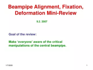
Beampipe Alignment, Fixation, Deformation Mini-Review 9.2. 2007 Goal of the review: Make ‘everyone’ aware of the critical manipulations of the central beampipe.
Beampipe Fixations Fixation SSW Fixation FMD2 Fixation FMD3 3400mm 1200mm
Beampipe Fixations • The beampipe is held in three points. Two of them (on both sides of the ITS) • are rotation points. The third one (on the FWD table) was originally assumed to be a fixed point. However we strongly favor a rotation point: • Beampipe is tested to maximum stress of 15MPa. This translates into a maximum allowed sag of 2.9(1.8)mm for a rotation(fixed) point, which we must not exceed in all circumstances. • The cables holding the beampipe are tensioned to 50N. • The force on the middle support is proportional to the beampipe sag and assumes 36(42)N at the maximum allowed stress of 15MPa. • Measuring this force tells us directly the sag of the beampipe without need for any optical alignment devices. F 3400mm 1200mm
Installation of Beampipe & Bakeout Shell Beampipe is supported in the bakeoutshell in two points O.K. 4600mm
1st beampipe fixation Removal of first section of bakeout shell. Alignment of beampipe on C-side. Still supported on two points O.K. Alignment 4600mm
1st beampipe fixation Fixation of beampipe on FMD3 cone. Monitoring of beampipe fixation 4600mm
1st beampipe fixation Monitoring of FMD3 beampipe fixation: BCAM looking at a reflective Prism fixed to the ITS structure Friedrich Lackner 4600mm
2nd beampipe fixation Strain Gauges Friedrich Lackner 3400mm 1200mm
Fixation 1 Fixation 2 Fixation 3 (on chariot) Line of sight for survey
Fixation 2 Fixation 3 (on chariot) 3400mm 1200mm
Movement of TPC to IP, 4.6m During the movement of the TPC to the IP, the ITS and the bakeout shell i.e. ALL beampipe support points, are sitting on the ITS rails. In theory, during the displacement of the TPC to the IP, the ITS rails, the ITS and the beampipe don’t move at all. They stay ‘fixed in space’. Because of imprecisions of the TPC movement, the three beampipe fixations points will move. Survey Survey+Strain Gauges Camera 3400mm 1200mm
Movement of TPC to IP Before movement of TPC, ITS is lifted by 3mm. This deforms the beampipe. 1200mm 3400mm 3mm sag=1mm
Movement of TPC to IP Final Test in Torino
Movement of TPC to IP When the TPC has arrived at the IP, the ITS is engaging with the fixation point on the TPC and the ITS is again lowered by 2mm. 1200mm 3400mm 1mm sag=0.3mm
Fixation of beampipe on A-side Beampipe chariot on A-side must be removed and the beampipe must be fixed to the TPC.
Fixation of beampipe on A-side First, the RF valve is fixed to the table.
Fixation of beampipe on A-side Valve Fixation Final Test in Torino.
Fixation of beampipe on A-side Valve Fixation Final Test in Torino.
Fixation of beampipe on A-side Removal of Beampipe Chariot.
Fixation of beampipe on A-side Removal of Beampipe Chariot.
Fixation of beampipe on A-side Temporary fixation of the beampipe. 3400mm 1200mm
Fixation of beampipe on A-side We want this fixation to be a rotation point. We designed a ‘very theoretical’ rotation point. It cannot withstand the 50kg vaccum force parallel to the beampipe. Longitudinal displacements of several mm. Changed to a simple clamp. A ‘bit’ of clearance will in reality always realize a rotation point.
Using strain gauges in the 4 cables we can directly monitor the beampipe sag. Since we have 4 cables we even know the exact direction of the sag and we have a redundant system (sum of the forces must always be zero). The VAC group agrees to this idea and the system will be developed by Friedrich Lackner (Ph.D. student TS/SU) early 2006. Such a system is crucial especially in view of the fact that we want to install TOF and TRD in presence of the beampipe.
1200mm 3400mm