Download
1 / 11
110 likes | 228 Views
Mechanical Constraints on the Beampipe Diameter. Ray Veness / TE - VSC. Introduction. Assuming The ATLAS, CMS (and ALICE?) would like to reduce the diameter of the central ~±3.5m of beampipe This new radius should be compatible with LHC Phase I upgrade

E N D
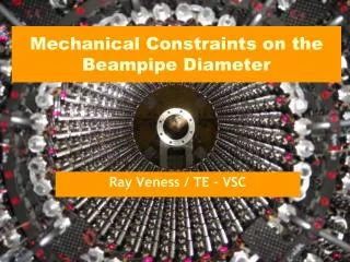
Mechanical Constraints on the Beampipe Diameter Ray Veness / TE - VSC
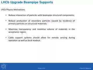
Introduction • Assuming • The ATLAS, CMS (and ALICE?) would like to reduce the diameter of the central ~±3.5m of beampipe • This new radius should be compatible with LHC Phase I upgrade • There are too many uncertainties to specify a geometry for Phase II upgrade • Then… (contents) • How did we reach the current beampipe radius? • What to the existing designs look like? • What have we learned since the beampipe was designed • What are possible ‘show stoppers’ on the way? • How long will it take to construct? Mechanical constraints - R.Veness
How the Start-up Beampipe was Specified • LHC Technical Committee 4/2/97 “… the LHCTC agreed there must be no question of the beampipe in an experiment introducing a potential performance limitation, in all cases adequate aperture and vacuum stability at maximum machine performance must be ensured.” • Beampipe was specified for ‘ultimate LHC’ in terms of: • Aperture • beam stay clear – for the tracker region, this was most critical at INJECTION • Tolerances to ensure beampipe does not enter beam stay-clear • dynamic vacuum • Beam lifetime, quench of triplet, beam-induced instabilities (ion-induced desorption, electron cloud etc) • Impedance • Transverse wall instabilities, trapped modes, resistive wall impedance • Background in the experiment – not a machine requirement • depends on machine layout, pressure in the whole insertion and requirement from the experiment – not linked the central diameter to the first order Mechanical constraints - R.Veness
Beampipe Diameter for LHC Baseline (1997 values) • Beam stay-clear 14mm • Composed of beam size, beam separation, closed orbit and crossing angle components • within the tracker region (±5 m) at injection • In forward regions, this may be higher for collision optics • Survey Precision ~ 2.6mm • See presentation from survey • Mechanical construction ~ 2.6mm • Tolerances on straightness, circularity, wall thickness, sag under self-weight and construction of survey targets • Instabilities ~ 9.8mm • Stability of the cavern, detector movements due to electro-magnetic forces and thermal expansion Mechanical constraints - R.Veness
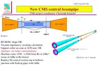
Baseline beampipe– the designs • Geometrical • ALICE, ATLAS and CMS beryllium pipes have the same basic geometry • 58mm inner diameter, 0.8mm wall thickness • This greatly simplified the development cost, tooling costs and spares inventory • With some differences • Beryllium lengths vary from 4 to 7 m • Transitions from beryllium to AA2219 in ATLAS and stainless steel in ALICE and CMS • Vacuum • Fully NEG (non-evaporable getter) coated and in-situ baked surface – low SEY, PDY, thermal outgassing • Gives a high distributed pumping speed for most gases seen in a UHV system • Sputter-ion pumps at outside central region for non-gettered gasses • Requires a certain beampipe diameter to provide conductance for non-NEG pumped gases • Electrical • Made from beryllium – low electrical resistivity, • no significant heating of chamber, no problems of transverse wall instabilities • No sharp transitions in geometry (no trapped modes etc) Mechanical constraints - R.Veness
ATLAS Central beampipe during integration on the pixel assembly bench Mechanical constraints - R.Veness
Central beampipe during in CMS Mechanical constraints - R.Veness
What have we learned since 1997? • Beam stay-clear: • Waiting for input from machine phase I upgrade studies • Survey precision • See talk from survey • Mechanical tolerances • Construction: Straightness, circularity, wall thickness • Better than expected • Sag under self-weight • Depends on number of supports, and supported weight • ATLAS would like to suppress one of 4 supports, and support the detector from the pipe • Will be larger than the baseline pipe in ATLAS • Precision of survey target construction • As expected • Instabilities • Cavern stability – see survey • Electro-magnetic and thermal movements • Survey input? • Will be know before we have feedback from operation with beam giving tracks? Mechanical constraints - R.Veness
Other Issues for a Reduction in Radius • Resistive wall beam heating • Calculated heat loss in 58mm ID beryllium chamber is 8.6 W/m for ultimate (0.9 A @ 7 TeV/c) machine [1] • Resistive wall impedance scales with 1/r3 (??) so decreasing the beampipe radius from 29 mm to 25 mm would increase heat load by 56% • Dynamic Vacuum • Reducing the diameter could lead to problems • Synchrotron radiation, pumping of non-NEG gases such as methane • However, engineering solutions outside the pixel should be possible, eg, SR masks, • Electron cloud effects, depending on bunch spacing • Other constraints linked to approaching the beam • Collimation, machine protection, background • These factors will be estimated once a provisional beampipe geometry is selected Mechanical constraints - R.Veness [1] L.Vos, Private communication
Contract timescale for Baseline beryllium pipes Chamber assembled ready for installation Engineering design agreed Installation in ATLAS starts Contract placed Call for tenders 2001 2002 2003 2004 2005 2006 2007 Market survey placed Finance committee approval for contract placement ATLAS chamber delivered to CERN CMS chamber delivered to CERN Total project duration: 6 years, 5 months Mechanical constraints - R.Veness
Summary • Beampipe radius • The mechanical tolerances were not a major factor in the composition of the beampipe radius • Considering the uncertainties remaining on the supporting systems and loads that the beampipe will have to support, it appears unwise to reduce them • Instabilities • This was the largest factor in the definition of the diameter after aperture • ‘Known unknowns’ such as stability of the cavern should be better understood • ‘Unknown unknowns’… will we know more before operation with beam? • Other parameters • As soon as we have a provisional geometry for the beampipe, we must feed this back to the relevant experts for analysis Mechanical constraints - R.Veness