Beampipe Support Structure
Beampipe Support Structure. October 2001 PST CDR E. Anderssen, LBNL. +X. +Z. +Y Vertical. Agreed Support Positions outside PST. PST Support Conditions Under Investigation. Chain of Support for PST to Cryostat. Side C. Side A. ID Flat Rail. View from top—all Tube Supports are

Beampipe Support Structure
E N D
Presentation Transcript
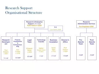
Beampipe Support Structure October 2001 PST CDR E. Anderssen, LBNL
+X +Z +Y Vertical Agreed Support Positions outside PST PST Support Conditions Under Investigation Chain of Support for PST to Cryostat Side C Side A ID Flat Rail View from top—all Tube Supports are Horizontal and Co-planar TRT SCT PIXEL SUPPORT TUBE Support Positions are shown, But constraint conditions are Not indicated here. ID Vee Rail Properties TBD Constraint TBD E. Anderssen LBNL
FEA Model – Important Features 10 45 End Support 30 Hoop Hat Stiffeners (section view) Bolt flanges End Supports Sct mount pads End Plugs (1 mm equiv. carbon sheet) E. Anderssen LBNL
Support Conditions of Beampipe • Beampipe Cruciform Supports align with Stiffest part of PST—the end flanges • All support planes on frame are wires allowing longitudinal (axial) float • One Z-Fixture is foreseen to take up ATLAS Access/Opening loads E. Anderssen LBNL
Gravity Sag Calculations Carbon Glass DY = .57 mm DY = 1.6 mm Whole Tube Sags at ends during operation—it is intended to ‘remove’ this sag when Reattaching supports after installation of Forward ID Note: Sag is with Package in place—much less without E. Anderssen LBNL
Service and Beampipe Support Service and Beampipe Support Pixel Package Assembly Mockup Pixel Frame shown E. Anderssen LBNL
Rail Design in Support Tube Vee and Flat rails were chosen to provide pseudo-kinematic support for the detector during delivery to the support points Rails are used only for delivery, not support mockup E. Anderssen LBNL
Tension/Compression Transmission through structures not services Clips register to Buttons on Frame and Service/Beampipe support structure Gaps allow ‘Phi’ offsets of up to +/- 1mm while only 0.25mm longitudinally E. Anderssen LBNL
Wire Planes supported by Pulleys Wires not modeled, beampipe not shown E. Anderssen LBNL
Tubes route cables to BarrelSeparate blocks at Forward end E. Anderssen LBNL
Services Supported By Framework E. Anderssen LBNL
Routing around Support Frame E. Anderssen LBNL
Need to adjust length of Tube or Support Plane location of VI E. Anderssen LBNL
Outside view of patch Panel E. Anderssen LBNL
Section View of patch Panel E. Anderssen LBNL
Barrel End of Support Structure E. Anderssen LBNL
Near term Goals • Increase detail of PP1/Endplug region • Analysis of Beampipe overhang is needed to understand if support locations are acceptable • Vibrational performance of Beampipe should be ascertained • Stiffness of Structure to be analyzed • Beampipe model produced and run with proposed design • Intend to have hand calculations by mid-November to verify this is right direction • Look to have first analysis iteration and better endplug detail by end of year—should leave enough time to iterate before beampipe FDR in Feb ‘02 E. Anderssen LBNL