Real-Time Document Clustering: Microprocessor Design and Implementation for Enhanced Performance
This project aims to develop a specialized microprocessor to efficiently cluster high-volume streams of documents in real-time. Traditional clustering algorithms face significant efficiency issues, often operating with O(n²d) complexity. Our solution involves designing a processor based on LEON2 that optimally executes clustering algorithms by reducing latency and leveraging dot-product computations. We aim to demonstrate improvements through a synthesized architecture on a liquid platform, enhancing document scoring with concept vectors while ensuring no compiler changes are necessary for application compatibility.


Real-Time Document Clustering: Microprocessor Design and Implementation for Enhanced Performance
E N D
Presentation Transcript
Team Members: Dan Legorreta Moshe Looks Shobana Padmanabhan Graduate Computer Architecture I Fall Semester 2005 Specialized Clustering Microprocessor Final Presentation
Cluster Project Goals • Long Term: Make it possible to cluster a high-volume stream of documents in real time. • This Course: Develop a specialized microprocessor which runs a specific clustering algorithm very efficiently.
Cluster Clustering • Problem • Clustering algorithms are currently very slow • ~ O(n2d) or worse • Spend a lot of time “scoring” the clusters • Scoring is done using “concept vectors” • A “concept vector” is the average/summation of a document vector
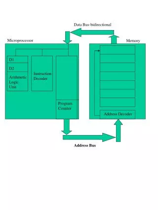
Cluster Solution • Develop a processor specifically designed for clustering • Base new processor on LEON2 • Modify processor to improve clustering application performance • Synthesize and demonstrate improvement on liquid architecture platform • Developed at Washington University, by ARL-FPX and DOC
Clustering as APB Device Cluster Clustering as Coprocessor Device LEON2 Processor • No compiler changes needed • But C application changes are needed • Lower latency with faster data bus
Cluster Circuit Design - Introduction Step 1: Represent documents as bit vectors Cluster X Cluster X Score = ? Score = ? Score = ? Score = ?
Cluster Circuit Design - Introduction Step 3: Compute the dot-product for each document Step 2: Compute the bit-wise sums Step 1: Represent documents as bit vectors Cluster X 1 0 1 0 1 1 1 0 0 1 ....... 0 1 0 0 1 0 1 = + 0 1 1 0 0 1 1 0 1 1 ....... 1 1 1 0 0 0 0 = + 1 0 0 1 1 0 1 0 1 1 ....... 0 1 0 1 1 1 0 = + 1 0 0 0 0 1 0 1 1 0 ....... 0 0 1 0 0 1 1 = = < - - - - - - - - - - 4000 Bits - - - - - - - - - - > Sums 3 1 2 1 2 3 3 1 2 3 ....... 1 3 2 1 2 1 2 3 =
Cluster 352 373 364 Circuit Design - Introduction Step 3: Compute the dot-product for each document Step 4: Analyze the quality of the cluster Cluster X 1 0 0 0 0 1 0 1 1 0 ....... 0 0 1 0 0 1 1 1 0 0 1 1 0 1 0 1 1 ....... 0 1 0 1 1 1 0 0 1 1 0 0 1 1 0 1 1 ....... 1 1 1 0 0 0 0 1 0 1 0 1 1 1 0 0 1 ....... 0 1 0 0 1 0 1 = x x x x x x x x x x x x Sums 3 1 2 1 2 3 3 1 2 3 ....... 1 3 2 1 2 1 2 = 3 0 2 0 2 3 3 0 2 0 2 DP = + + + + + + + + + + + ....... Score 365 DP = = 365
Cluster Circuit Design - Introduction Step 4: Analyze the quality of the cluster Scored Cluster X 365 373 352 364
Cluster Circuit Design - Limitations • Coprocessor Interface • Inputs • Data 1 – 64 bits • Data 2 – 64 bits • Opcode – 9 bits • Outputs • Result – 64 bits • Latency • 4 clock cycles between each opcode • Cannot access main memory directly
Cluster < - 4000 Bits - > 101010101010110100010101010101010100101000101011010111010011101010111010101010101010010100110010 011010101010101101000101010101010101001010001010110101110100111010101110101010101010100101001100 001010110101010101011010001010101010101010010100010101101011101001110101011101010101010101001010 101010101010101010110100010101010101010100101000101011010111010011101010111010101010101010010100 ….. 101010101101010101010110100010101010101010100101000101011010111010011101010111010101010101010010 N Documents 101010101010110100010101010101010100101000101011010111010011101010111010101010101010010100110010 011010101010101101000101010101010101001010001010110101110100111010101110101010101010100101001100 001010110101010101011010001010101010101010010100010101101011101001110101011101010101010101001010 101010101010101010110100010101010101010100101000101011010111010011101010111010101010101010010100 101010101101010101010110100010101010101010100101000101011010111010011101010111010101010101010010 Circuit Design – 1st Approach • Bitwise Sum • Dot Product • 32 Additional Coprocessor commands • ≈ .5 kb of memory needed per document sums Coprocessor Commands: 32 +32 +32 +32 +32 + ………. +32 +32 +32 +32 +32 +32 = 32 * N
Cluster 101010101010110100010101010101010100101000101011010111010011101010111010101010101010010100110010 Full Dot Product Local Memory < - 64 Bits - > < - 64 Bits - > Partial Dot Product < - 64 Bits - > Dot-Product Circuit 011010101010101101000101010101010101001010001010110101110100111010101110101010101010100101001100 001010110101010101011010001010101010101010010100010101101011101001110101011101010101010101001010 101010101010101010110100010101010101010100101000101011010111010011101010111010101010101010010100 ….. 101010101101010101010110100010101010101010100101000101011010111010011101010111010101010101010010 N Documents 101010101010110100010101010101010100101000101011010111010011101010111010101010101010010100110010 011010101010101101000101010101010101001010001010110101110100111010101110101010101010100101001100 001010110101010101011010001010101010101010010100010101101011101001110101011101010101010101001010 101010101010101010110100010101010101010100101000101011010111010011101010111010101010101010010100 101010101101010101010110100010101010101010100101000101011010111010011101010111010101010101010010 10101010101010101011 10010101100101010010 10101010101010101011 10010101100101010010 10101010101010101011 10101010101010101011 10010101100101010010 10101010101010101011 10010101100101010010 10101010101010101011 Circuit Implementation sums sums sums 10101010101010101011 10010101100101010010 10101010101010101011 10010101100101010010 10101010101010101011 10101010101010101011 10010101100101010010 10101010101010101011 10010101100101010010 10101010101010101011 sums
Cluster Circuit Diagram
Cluster Circuit Testing • C program uses inline assembly to issue coprocessor/ dot-product opcodes • Compiled using Liquid development platform, to use sparc-elf-gcc for LEON • Platform creates IP packet based simulation files for ModelSim • Platform uses Synplicity to synthesize, Xilinx tools for building and place-n-route, and creates a bit file • To test on hardware, Liquid web interface to • load program into SRAM • start LEON (execute program) • Read memory, to read results
Cluster Circuit Testing – C Program long long op1 = 0x0E000000000000001F; long long op2 = 0x190000000000000022; // Inline assembly to load address of C vars into gen purpose registers asm(" mov %0, %%l0" : : "r" (&op1)); // Place op1 address in %l0 asm(" mov %0, %%l1" : : "r" (&op2)); // Place op2 address in %l1 asm(" mov %0, %%l2" : : "r" (&result)); // Place result addres in %l2 // Load 64-bit op1 value into (%c0,%c1), 64-bit op2 value into (%c2,%c3) asm("ldd [%l0], %c0"); asm("ldd [%l1], %c2"); // Load Interal Coprocessor Register 0 with 128-bit value (%c2 & %c1) asm(cpop1(HCLUST_STG1, "0x00", "0x02", "0x30")); // Store 64-bit value from coproc register file location %c3 to result[0] asm("set 0x40040040, %l2"); // Set bit mask asm("std %c3, [%l2]"); //Store 64-bit value from coproc reg file at (%c1e,%c1f) to result[0]
Cluster Circuit Testing • Test cluster contains 4 128 bit vectors • Document 1 = 0x0E000000000000001F • Document 2 = 0x190000000000000022 • Document 3 = 0x220000000000000019 • Document 4 = 0x1F000000000000000F • Expected scores • Document 1 = 0x15 • Document 2 = 0x0B • Document 3 = 0x0C • Document 4 = 0x17
Cluster Circuit Testing - Inputs 1st Set of Inputs: 0E 19 2nd Set of Inputs 22 1F 3rd Set of Inputs 1F 22 4th Set of Inputs 19 0F
Cluster Circuit Testing - Outputs 1st Set of Results 15 0B 2nd Set of Results 0C 17
Cluster Performance Gain Estimate • Assuming n data points, data dimensionality (k) is 4000 • Unaccelerated (lower bound) • Summation: = 4,000*n cycles • Dot Product: = 8,000*n cycles • Total: = 12,000*n cycles • Accelerated (upper bound) • Stage One: (1.5 * n) * k / 64 = 95*n cycles • Stage Two: 2 * k / 64 = 125 cycles • Stage Three: 4 * n = 4*n cycles • Total: = 97*n + 125 cycles • Clustering is hierarchal, so cumulative speedup factor is: • At least: 12,000 / (97 + 125) ~= 54 • At most: 12,000 / 97 ~= 124
Cluster Questions
Progress – part 1: Clustering App Cluster • Modified clustering application to run on Leon • Challenges • 25 MHz • No OS and so no system calls, no I/O, only 4MB SRAM & 32KB icache & dcache each • Recursion/ function calls restricted to 7 levels • No debugger, other than reading from memory • Some of these addressed with a new cross-compiler but profiler not upgraded for the new cross-compiler
Cluster Progress – part 2: APB device • Implemented APB device interface • Challenges • Huge Leon code-base • Integrate the device, decode memory-mapped registers • Designed dot-product circuit to gain 50% speedup • But for more speedup, we switched to Co-processor interface
Cluster Progress – part 3: Co-processor • Extended hardware implementation to do scoring besides dot-product. • Prof. Young helped with design. • Implemented both circuits (3 stages). • Tested integration of stage1 with LEON.
Cluster Sample C code for APB // Dot-product Device Registers int *PDevice_Init = (int *) 0x800000D0; // Initailize Device int *PDevice_Status = (int *) 0x800000D0; // Device Status int *PDevice_Data = (int *) 0x800000D4; // Device Input int *PDevice_Length = (int *) 0x800000D8; // Device Result int recieveBuffer[300]; // Store the result main() { PDevice_Init[0] = 0; if (PDevice_Status[0] == 0) { recieveBuffer[0] = PDevice_Data[0]; } }
Cluster APB Device
Cluster Co-processor