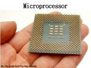
Microprocessor
Microprocessor. AVR microcontroller & Intel microprocessors. 강의계획. 전반기 : AVR ATmega128 Microcontroller Architecture 후반기 : Intel microprocessor architectures including microarchitectures of P6 family and multi-core processors. AVR Microcontroller. Overview of AVR microcontroller.


Microprocessor
E N D
Presentation Transcript
Microprocessor AVR microcontroller & Intel microprocessors
강의계획 • 전반기: AVR ATmega128 Microcontroller Architecture • 후반기: Intel microprocessor architectures including microarchitectures of P6 family and multi-core processors
Overview of AVR microcontroller • Single-chip microcomputer • AVR Alf Vergard Risc • RISC-based low-power 8-bit microprocessor with multiple I/O ports and various peripheral modules (e.g., A/D converter, timer/counter, serial data interfaces, etc) • Low power consumption, low cost & small size suitable for embedded systems and ubiquitous sensor networks
Main applications of microcontrollers • building, industrial, and climate control • hand-held battery applications • factory automation • networking • home appliances • optical and medical devices • Automotives • Battery management
General Features of AVR µ-C • Provides the highest MIPS/mW • RISC-based architecture : includes the large number of registers, and most of instructions are executed in a single cycle • Adopted Harvard architecture to maximize performance and parallelism : uses separated memory and bus for program and data • Program codes are stored in a reprogrammable flash memory • All instructions are in 16-bit format, thus each location of flash memory contains a 16-bit instruction
AVR microcontroller series [1]<http://www.atmel.com/products/microcontrollers/avr/> • 32-bit AVR UC3 series • General-purpose 32-bit microcontroller • 16~512KB flash memory • Up to 66 MHz, 1.5 MIPS/MHz • Low power consumption (picoPower tech) • Sleep walking intelligent peripherals • Peripheral event system(DMA) • Clock failure protection • 12-bit Analog-to-Digital converter
AVR microcontroller series [2]<http://www.atmel.com/products/microcontrollers/avr/> • 8/16-bit AVR XMEGA series • General-purpose 8-bit/16-bit microcontroller • 16~384 KB flash memory • Up to 32 MHz, 1.0 MIPS/MHz • Low power consumption (picoPower tech) • Sleep walking intelligent peripherals • Peripheral event system(DMA) • Includes AES and DES crypto modules • 12-bit Analog-to-Digital converter
AVR microcontroller series [3]<http://www.atmel.com/products/microcontrollers/avr/> • 8-bit megaAVR series • General-purpose 8-bit microcontroller • 4~256 KB flash memory • Up to 20 MHz, 1.0 MIPS/MHz • Low power consumption (picoPower tech) • Sleep walking intelligent peripherals • 8-bit Analog-to-Digital converter • Suitable for mid-scale or large-scale systems that need the large number of I/O peripherals and interfaces
AVR microcontroller series [4] <http://www.atmel.com/products/microcontrollers/avr/> • 8-bit tinyAVR series • Suitable for small systems(smallest chip: 1.5mmx1.4mm) • 0.5~8 KB flash memory
AVR microcontroller series [5] <http://www.atmel.com/products/microcontrollers/avr/> • Battery Management series • Suitable for Li-Ion Battery management • 1.8~25V operation • Designed to maximize lifetime and energy per cycle • Includes dedicated analog-to-digital converters tailored for battery fuel gauging and voltage monitoring • Enables utilization of the entire battery capacity without unplanned shut-downs
AVR microcontroller series [6] <http://www.atmel.com/products/microcontrollers/avr/> • Automotive AVR series • Suitable for automotive environment • picoPower • Sleepwalking peripherals • 8-bit or 32-bit CPUs • Various types of microcontrollers
Features of ATmega128 • High-performance, low-power AVR 8-bit Microcontroller • Advanced RISC Architecture – 133 Powerful Instructions : Mostly Single Clock Cycle Execution – 32 x 8 General Purpose Working Registers & Peripheral Control Registers – Up to 16 MIPS Throughput at 16 MHz – On-chip 2-cycle Multiplier
Features of ATmega128 • Memories – 128K Bytes of In-System Reprogrammable Flash Endurance: 10,000 Write/Erase Cycles – 4K Bytes EEPROM Endurance: 100,000 Write/Erase Cycles – 4K Bytes Internal SRAM – Up to 64K Bytes Optional External Memory Space – Programming Lock for Software Security – SPI Interface for In-System Programming
Features of ATmega128 (cont’d) •Peripheral Devices – Two 8-bit Timer/Counters with Separate Prescalers and Compare Modes – Two Expanded 16-bit Timer/Counters with Separate Prescaler, Compare Mode and Capture Mode – Real-Time Counter with Separate Oscillator – Two 8-bit PWM Channels – 6 PWM Channels with Programmable Resolution from 2 to 16 Bits – Output Compare Modulator
Features of ATmega128 (cont’d) •Peripheral Devices (cont’d) – 8-channel, 10-bit ADC 8 Single-ended Channels 7 Differential Channels 2 Differential Channels with Programmable Gain at 1x, 10x, or 200x – Byte-oriented Two-Wire Serial Interface – Dual Programmable Serial USARTs – Master/Slave SPI Serial Interface – Programmable Watchdog Timer with On-chip Oscillator – On-chip Analog Comparator
Features of ATmega128 (cont’d) •Special Features – Power-on Reset and Programmable Brown-out Detection – Internal Calibrated RC Oscillator – External and Internal Interrupt Sources – Six Sleep Modes: Idle, ADC Noise Reduction, Power- save, Power-down, Standby, & Extended Standby – Software Selectable Clock Frequency
Features of ATmega128 (cont’d) •I/O and Packages – 53 Programmable I/O Lines • Operating Voltages – 2.7 - 5.5V for ATmega128L – 4.5 - 5.5V for ATmega128 • Speed Grades – 0~8 MHz for ATmega128L – 0~16 MHz for ATmega128
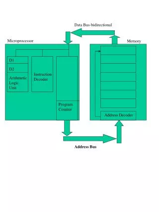
AVR CPU core • In order to maximize performance and parallelism, the AVR uses a Harvard architecture (with separate memories and buses for program and data) • Program memory : In-system reprogrammable flash memory (128Kbytes) • Data memory : SRAM, 4 Kbytes (internal) & up to 64 Kbytes (external)
AVR CPU core (cont’d) • Most AVR instructions have a single 16-bit word format Every program memory address contains a 16-bit or 32-bit instruction • Program Flash memory space is divided into two sections • Boot Program section • Application Program section (Both sections are protected by dedicated Lock bits for write and read/write)
AVR CPU core (cont’d) • During interrupts and subroutine calls, the return address (in PC) is stored on the stack • Stack is allocated in the data memory SRAM. Its size is limited by the size of SRAM • Stack Pointer(SP) is read/write accessible in the I/O space. All user programs must initialize the SP in the reset routine (before subroutine or interrupts are executed)
AVR CPU core (cont’d) • Interrupt • Each interrupt module has its control registers in the I/O space with an additional global interrupt enable bit in Status Register • All interrupts have a separate interrupt vectorin the interrupt vector table (p.57) • Interrupts have priority in accordance with their vector in the vector table position. The lower the interrupt vector address, the higher the priority
AVR CPU core (cont’d) • I/O memory space contains 64 addresses($20 ~ $5F) which can be accessed directly, or as the Data Space locations following those of the Register file • ATmega128 also has Extended I/O space from $60 ~ $FF where only the ST/STS/STD and LD/LDS/LDD instructions can be used(Refer to Register Summary on pp. 364~366 in the text)
Register file : 32 8-bit general-purpose registers with a single clock cycle access time allows single-cycle ALU operations
R26 … R31 functions, in addition to general purpose, as 16-bit address pointers for (register) indirect addressing of the Data Space • X register : R26 & R27 • Y register : R28 & R29 • Z register : R30 & R31
ALU • Performs arithmetic, logic, and bit operations • Directly connected with all the 32 general-purpose registers • Single cycle ALU operation(two operands are read from registers, an ALU operation is executed, and the result is stored back in the register file)
Status Register(SREG) : $3F($5F) • contains information about the result of the most recently executed arithmetic instruction • Status register is not automatically stored when entering an interrupt routine and restored when returning from an interrupt. This must be handled by S/W
Status Register (cont’d) • Bit 7 (I) : Global Interrupt Enable. If this bit is cleared, none of the interrupts are enabled independent of the individual interrupt enable settings. I-bit is cleared by H/W after an interrupt has occurred, and is set by the RETI instruction to enable subsequent interrupts. And it is also set and cleared in S/W with SEI and CLI instructions
Status Register (cont’d) • Bit 6 (T) : Bit Copy Storage. Bit copy instructions BLD (Bit LoaD) and BST(Bit Store) use the T-bit as source or destination for the operated bit. BLD – copy a bit from a register into TBST – copy a bit in T into a bit in a register • Bit 5 (H) : Half carry flag • Bit 4 (S) : Sign bit (N xor V) <refer to the instruction set manual> • Bit 3 (V) : 2’s complement overflow flag • Bit 2 (N) : Negative flag (R7 bit) • Bit 1 (Z) : Zero flag (set to 1 if the result is 0) • Bit 0 (C) : Carry flag
Stack Pointer(SP) • Stack is used for storing • temporary data • local variables • return addresses after interrupts and subroutine calls • SP register points to the top of the stack • Stack space in data SRAM must be defined by the program before any subroutine calls are executed or interrupts are enabled • SP is decremented after PUSH instruction, & incremented after POP instruction
Stack Pointer (cont’d) • AVR SP is implemented as two 8-bit registers in the I/O space : $3D($5D), $3F($5E)
Instruction Execution Timing • Instruction execution : single-level pipelining (2-stage pipelining)
Reset and interrupt handling • Lowest addresses in the program memory space are by default defined as the Reset and Interrupt vectors(complete list of vectors is shown on page 57) • The lower the address, the higher the priority level • RESET has the highest priority • Example of using I flag to enable/disable an interrupt: text (p.14) • Interrupt response time: 4 clock cycles (p.15)