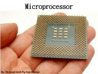
Understanding Microprocessor Interrupts and Signals
Learn about interrupts, maskable interrupts, non-maskable interrupts, and signals in microprocessors along with detailed explanations of registers and interrupt handling mechanisms.


Understanding Microprocessor Interrupts and Signals
E N D
Presentation Transcript
Interrupts • The processor has 5 interrupts. • CALL instruction (3 byte instruction). The processor calls the subroutine, address of which is specified in the second and third bytes of the instruction. • RST5.5 is a maskable interrupt. When this interrupt is received the processor saves the contents of the PC register into stack and branches to 2CH (hexadecimal) address. • RST6.5 is a maskable interrupt. When this interrupt is received the processor saves the contents of the PC register into stack and branches to 34H (hexadecimal) address.
Interrupts (cont..) • RST7.5 is a maskable interrupt. When this interrupt is received the processor saves the contents of the PC register into stack and branches to 3CH (hexadecimal) address. • TRAP is a non-maskable interrupt. When this interrupt is received the processor saves the contents of the PC register into stack and branches to 24H (hexadecimal) address. • All maskable interrupts can be enabled or disabled using EI and DI instructions. RST 5.5, RST6.5 and RST7.5 interrupts can be enabled or disabled individually using SIM instruction.
Signals • RESET IN : When this signal goes low, the program counter (PC) is set to Zero, μp is reset and resets the interrupt enable and HLDA. • RESET OUT: This signal indicates that μp is being reset. This signal can be used to reset other devices. The signal is synchronized to the processor clock and lasts an integral number of clock periods. • SID - Serial Input Data Line: The data on this line is loaded into accumulator bit 7 when ever a RIM instruction is executed. • SOD – Serial Output Data Line: The SIM instruction loads the value of bit 7 of the accumulator into SOD latch if bit 6 (SOE) of the accumulator is 1.
DMA Signals • HOLD: Indicates that another master is requesting the use of the address and data buses. The CPU, upon receiving the hold request. • HLDA: Hold Acknowledge : Indicates that the CPU has received the HOLD request and that it will relinquish the bus in the next clock cycle. • READY : This signal Synchronizes the fast CPU and the slow memory, peripherals. • If READY is high during a read or write cycle, it indicates that the memory or peripheral is ready to send or receive data. • If READY is low, the CPU will wait an integral number of clock cycle for READY to go high before completing the read or write cycle.
Registers • Accumulator or A register is an 8-bit register used for • arithmetic, logic, I/O and load/store operations. • Flag Register has five 1-bit flags. • Sign - set if the most significant bit of the result is set. • Zero - set if the result is zero. • Auxiliary carry - set if there was a carry out from bit 3 to bit 4 of the result. • Parity - set if the parity (the number of set bits in the result) is even.
Registers (cont..) • Carry - set if there was a carry during addition, or borrow during subtraction/comparison/rotation. General Registers: • 8-bit B and 8-bit C registers can be used as one 16-bit BC register pair. When used as a pair the C register contains low-order byte. Some instructions may use BC register as a data pointer. 8-bit D and 8-bit E registers can be used as one 16-bit DE register pair. When used as a pair the E register contains low-order byte. Some instructions may use DE register as a data pointer.