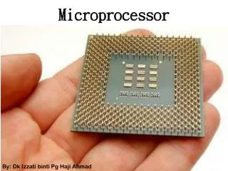
Microprocessor
This chapter delves into the architecture and functionality of the 6800 microprocessor, a critical component in computer systems. It covers topics including CPU components like the Arithmetic Logic Unit, memory types (RAM, ROM, etc.), and various input/output devices. We explore the concept of instruction execution, including opcode and operand structure, basic addressing modes, the significance of the stack pointer, and interrupt handling. Practical examples demonstrate how to write simple assembly language programs while detailing the machine code required for execution.


Microprocessor
E N D
Presentation Transcript
Microprocessor Chapter 2 The 6800 microprocessor
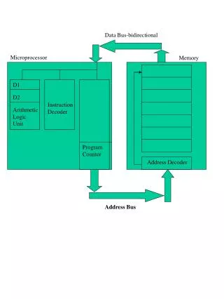
A Typical Computer Architecture (follow the links for explanations of the terms) Serial Devices (e.g. Modem) • Input Devices • Keyboard • Mouse • Scanner Parallel Devices (e.g. Printer) • Output Devices • Monitor • Loudspeaker Serial Port Driver Parallel Port Driver Control Bus Address Bus Data Bus CPU Program Counter Controller Arithmetic and Logic Unit • File Storage • Hard Disk • Floppy Disk • Tape • CD Clock • Memory • RAM • ROM • PROM Control Unit
Microprocessor Characteristics • Number of address wires • Number of data wires • Speed • Architecture • Language (Assembly language)
Characteristics of the 6800 Microp. • 16 address wires => it can address 216 memory locations • It is an 8 bit microprocessor => 8 data bits • Speed may be 4 MHZ • Architecture??
6800 architecture • Architecture: • Registers • Logic and Arithmetic unit • Control unit • Program counter • Stack pointer • …
6800 registers Accumulator A Accumulator B Index Register X=XH : XL Stack Pointer, SP Program Counter, PC Condition Code Data bus from and to memory Instruction register 8 Control unit Temp 8 8 ALU Address wires from PC
PC: Program counter • Program counter contain the address of the memory containing the next instruction to be executed. • It is incremented automatically after each instruction • In 6800, it is a 16 bits register
First instruction: ABA • ABA: opcode=?? • First, the instruction is fetched in the instruction register (IR is used to fixx the command for the control unit during processing) • The control unit command the registers in the following way: • Command register A to put its contain on the internal bus • Command the register TEMP to take the data on the bus • Command the register B to put its contain on the bus • Command the ALU to add • Command A register to take the result
instruction • LDA A #$90 86 90 • If this instruction is written in the memory address: $5000, the program counter contain $5000 when executed. • Procedure: • PC=5000 so the data 86, read from this memory address, goes to the instruction register • The control unit analyse this data and command the registers: • Command the PC to be incremented, the data $90 in the address $5001 can be read now. Data are on the internal bus • Command the register A to take these Data
Example • Add: $3D and $E2 0011 1101 1110 0010 ------------- 1 0001 1111 C=1, Z=0, V=0, N=0 H=0
Example • Add: $BD and $A3 1011 1101 1010 0011 ------------- 1 0110 0000 C=1, Z=0, V=1, N=0 H=1
Some instructions Instruction = Opcode + Operand • LDA A #$4E = 86 4E • STA A $2EA5 B7 2E A5 Opcode Operand Opcode Operand
First program • Write a program which can add the register A to $4E and then put the result in the memory location $2346 • Find the machine code of this program
Program • Write a program which can add the two numbers: $2E and $8A and put the result in the memory location 349A
Stack pointer SP • Used to point to the memory location where all registers will be saved when an interrupt occurs or when a subroutine is called • It is a 16 bit register, contain an address of a memory
Interrupt • During the processing of a program, the microprocessor can stop its work and execute another emergency program. This is the technique of interrupt. • 2 hardware pins can be found in the 6800 microprocessor: IRQ and NMI (both active low) • IRQ: interrupt request • NMI: Non maskable interrupt • If IRQ occurs, the address of its corresponding program is written in : FFF8 and FFF9 • If NMI occurs, the address of its corresponding program is written in : FFFC and FFFD
Interrupt • IRQ may be stopped by the bit I in the status register • I=1 IRQ will not be executed (stopped) • I=0 IRQ will be executed • NMI non maskable interrupt, it is executed whatever the bit I • SWI is a software interrupt: Program address: FFFA and FFFB
Addressing modes • Immediate mode LDA A #$89 A=$89 LDA B #$F3 B=$F3 • Inherent mode ABA A+B A INCA A+1A DECB B-1B INS S+1S
Addressing modes • Extended mode (2 bytes operand) LDA A $15CD STA A $078C • Direct mode (one byte operand) LDA $12 Equilvalent to LDA $0012
Adresing modes • Indexed (using X register. LDA A $05,X STA A $08,X This register is used as a base address when we want to make the addressing for a series of successive memories
Addressing modes • Relative mode (Branch instructions) BEQ: Branch if equal: if z=1 BNE : branch if not equal : if z=0 BME : branch if minus: if N=1 B PL: branch if positive : if N=0 BCS : branch if carry set : if C=1 BCC : branch if carry clear : if C=0
Program LDA A #$89 LDA B $6789 INC A BPL here STA A $1928 INCB LDX #$98F5 here STA A $09 LDX #$9000 RTS Write the machine code of this program
Instructions • ADD • SUB • …
Instructions • ROR • ROL • Stack pointer instructions • PUSH • PULL
Programs • P1: write a program to add the memory contents: from A9F0 to A9FF and put the result in the memory location 0002. • P2: write a program to transfer the memory contents: from 9000 - 90FF to A000 - A0FF. • Write a program to compute the integer part of: (1+2+4+8+16)/4
A program CLI LDA A #$26 LDX $2608 LDA B $02,X (IRQ arrives here) CMP A $25FE BNE here ABA RTS here TAB RTS Interrupt program 1 5040: LDA A #$50 LDA B $2602 ABA RTI
6800 Pins • power and ground • Address bus (A0-A15) • tri-state: controlled by BA or TSC • VMA (valid memory address) and dummy access • Data bus (D0-D7) • R/W – high impedance if BA=1 and TSC is asserted • Reset, HALT, NMI, IRQ • BA (bus available), BS (bus status): • normal (00), interrupt or reset acknowledge (01), sync acknowledge (10), and halt acknowledge(11) • Clocks E and Q
6800 Pins (continued) • Busy: • read and modify cycles, double-byte operation, indirect or vector fetch • AVMA: advance VMA • MPU will use the bus in the following cycle • LIC: last instruction cycle • instruction fetch if transitions from high to low • TSC: three-state control • direct control when E is low • latched on the rising edge of E