Advanced Lithography Techniques: Enhancing Substrate Imaging Quality
580 likes | 937 Views
Explore lithographic processes, photo masks, and printing methods in semiconductor fabrication. Learn about resolution limits, optics complexity, and tradeoffs in projection lithography. Discover negative and positive resists and the impact of exposure sources on lithography. Dive into immersion lithography benefits, like improved resolution and increased depth of focus. Understand image quality metrics like contrast and explore the mechanisms of positive and negative resists.

Advanced Lithography Techniques: Enhancing Substrate Imaging Quality
E N D
Presentation Transcript
Section 2: Lithography Jaeger Chapter 2 Litho Reader EE143 – Ali Javey
The lithographic process EE143 – Ali Javey
Substrate covered with silicon dioxide barrier layer Positive photoresist applied to wafer surface Mask in close proximity to surface Substrate following resist exposure and development Substrate after etching of oxide layer Oxide barrier on surface after resist removal View of substrate with silicon dioxide pattern on the surface Photolithographic Process EE143 – Ali Javey
Composite drawing of the masks for a simple integrated circuit using a four-mask process Drawn with computer layout system Complex state-of-the-art CMOS processes may use 25 masks or more Photomasks - CAD Layout EE143 – Ali Javey
Example of 10X reticle for the metal mask - this particular mask is ten times final size (10 mm minimum feature size - huge!) Used in step-and-repeat operation One mask for each lithography level in process Photo Masks EE143 – Ali Javey
Lithographic Process EE143 – Ali Javey
Printing Techniques Contact printing Proximity printing Projection printing • Contact printing damages the mask and the wafer and limits the number of times the mask can be used • Proximity printing eliminates damage • Projection printing can operate in reduction mode with direct step-on-wafer EE143 – Ali Javey
Resolution R < 0.5m mask plate is easily damaged or accumulates defects Contact Printing hv Photo Mask Plate photoresist wafer EE143 – Ali Javey
Proximity Printing hv Photoresist g~20m exposed wafer R is proportional to ( g ) 1/2 ~ 1mm for visible photons, much smaller for X-ray lithography EE143 – Ali Javey
Projection Printing hv De-Magnification: nX 10X stepper 4X stepper 1X stepper lens focal plane P.R. wafer ~0.2 mm resolution (deep UV photons) tradeoff: optics complicated and expensive EE143 – Ali Javey
Diffraction EE143 – Ali Javey
Aerial Images formed by Contact Printing, Proximity Printing and Projection Printing EE143 – Ali Javey
Photon Sources EE143 – Ali Javey
Optical Projection Printing Modules Optical System: illumination and lens Resist: exposure, post-exposure bake and dissolution Mask: transmission and diffraction Wafer Topography: scattering Alignment:
Optical Stepper EE143 – Ali Javey
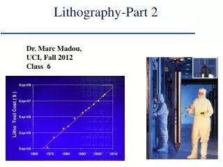
Resolution in Projection Printing f = focal distance d = lens diameter Minimum separation of a star to be visible.
Resolution limits in projection printing EE143 – Ali Javey
Depth of Focus (DOF) point EE143 – Ali Javey
Example of DOF problem Photo mask Field Oxide Different photo images EE143 – Ali Javey
Tradeoffs in projection lithography (1) and (2) require a compromise between and NA ! EE143 – Ali Javey
Pattern transfer of two closely spaced lines Conventional mask technology - lines not resolved Lines can be resolved with phase-shift technology Sub-resolution exposure: Phase Shifting Masks EE143 – Ali Javey
Immersion Lithography • A liquid with index of refraction n>1 is introduced between the • imaging optics and the wafer. • Advantages • Resolution is improved proportionately to n. For water, the index of refraction at l = 193 nm is 1.44, improving the resolution significantly, from 90 to 64 nm. • 2) Increased depth of focus at larger features, even those that are printable with dry lithography. EE143 – Ali Javey
Image Quality Metric: Contrast Contrast is also sometimes referred as the Modulation Transfer Function (MTF) EE143 – Ali Javey
Questions: How does contrast change as a function of feature size? How does contrast change for coherent vs. partially coherent light? EE143 – Ali Javey
Image Quality metric: Slope of image * simulated aerial image of an isolated line EE143 – Ali Javey
The need for high contrast EE143 – Ali Javey
Resists Positive Negative Exposure Sources Light Electron beams Xray sensitive Resists for Lithography EE143 – Ali Javey
Negative Resist Composition: Polymer (Molecular Weight (MW) ~65000) Light Sensitive Additive: Promotes Crosslinking Volatile Solvents Light breaks N-N in light sensitive additive => Crosslink Chains Sensitive, hard, Swelling during Develop Positive Resist Composition Polymer (MW~5000) Photoactive Dissolution Inhibitor (20%) Volatile Solvents Inhibitor Looses N2 => Alkali Soluble Acid Develops by “etching” - No Swelling. Two Resist Types EE143 – Ali Javey
Positive P.R. Mechanism Photons deactivate sensitizer dissolve in developer solution polymer + photosensitizer EE143 – Ali Javey
Positive Resist Q Q 0 f 1 º Resist contrast Q æ ö f log ç ÷ Q 10 è ø 0 EE143 – Ali Javey
Negative P.R. Mechanism Q Q f 0 hv => cross-linking => insoluble in developer solution. EE143 – Ali Javey
Positive P.R.: higher resolution aqueous-based solvents less sensitive Negative P.R.: more sensitive => higher exposure throughput relatively tolerant of developing conditions better chemical resistance => better mask material less expensive lower resolution organic-based solvents Positive vs. Negative Photoresists EE143 – Ali Javey
+ + + + Overlay Errors alignment mask wafer photomask plate Alignment marks from previous masking level EE143 – Ali Javey
(1) Thermal Run-in/Run-out errors run-out error wafer radius EE143 – Ali Javey
Rotational / Translational Errors (2) Translational Error image Al n+ referrer p (3) Rotational Error EE143 – Ali Javey
Overlay implications: Contacts EE143 – Ali Javey
Overlay implications: Gate edge EE143 – Ali Javey
Total Overlay Tolerance si= std. deviation of overlay error for ith masking step stotal= std. deviation for total overlay error Layout design-rule specification should be> stotal EE143 – Ali Javey
Standing Waves EE143 – Ali Javey
Standing waves in photoresists x d P.R. SiO2/Si substrate m = 0, 1, 2,... Intensity = minimum when m = 1, 3, 5,... Intensity = maximum when n = refractive index of resist EE143 – Ali Javey
Proximity Scattering EE143 – Ali Javey
Approaches for Reducing Substrate Effects • Use absorption dyes in photoresist • Use anti-reflection coating (ARC) • Use multi-layer resist process • 1: thin planar layer for high-resolution imaging • 2: thin develop-stop layer, used for pattern transfer to 3 • 3: thick layer of hardened resist (imaging layer) (etch stop) (planarization layer) EE143 – Ali Javey
Electron-Beam Lithography Angstroms for V in Volts Example: 30 kV e-beam => l = 0.07 Angstroms NA = 0.002 – 0.005 Resolution < 1 nm But beam current needs to be 10’s of mA for a throughput of more than 10 wafers an hour. EE143 – Ali Javey
Types of Ebeam Systems EE143 – Ali Javey
Resolution limits in e-beam lithography EE143 – Ali Javey
The Proximity Effect EE143 – Ali Javey