Download
1 / 30
360 likes | 903 Views
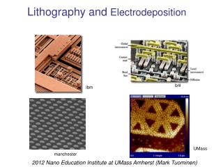
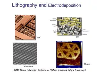
Lithography (and briefly, Electrodeposition). bnl. ibm. UMass. manchester. July 10, 2008: Nano Education Institute at UMass Amherst . Self Assembly (inspired by nature). Lithography (designed by humans). How do we control the shape and size of nanostructures?. Nanostructures.

E N D
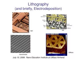
Lithography (and briefly, Electrodeposition) bnl ibm UMass manchester July 10, 2008: Nano Education Institute at UMass Amherst
Self Assembly (inspired by nature) Lithography (designed by humans) How do we control the shape and size of nanostructures?
Nanostructures nanofilm, or nanolayer (2D) macroscale (3D) object height depth width nanoparticle, nanodot, quantum dot (0D) nanowire, nanorod, or nanocylinder (1D)
Computer Microprocessor "Heart of the computer" Does the "thinking"
Making Small SmallerAn Example: Electronics-Microprocessors microscale nanoscale macroscale ibm.com
An example of a FILM A monolayerNANOFILM (single layer of molecules) ~1 nm thick Langmuir film This is an example of SELF-ASSEMBLY
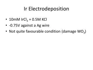
Working Electrode (WE) Counter Electrode (CE) "oxidation" Cu(0) –> Cu2+ + 2e- ("electroplating") Nanofilm by Electrodeposition I V cathode anode CuSO4 dissolved in water If using an inert Pt electrode: 2 H2O –> O2 + 4H+ + 4e- "reduction" Cu2+ + 2e- –> Cu(0)
A nanofilm method,Thermal Evaporation sample QCM Vaporization or sublimation of a heated material onto a substrate in a vacuum chamber film vapor Au, Cr, Al, Ag, Cu, SiO, others Pressure must be held low to prevent contamination! vacuum ~10-7 torr source There are many other thin film manufacturing techniques resistive, e-beam, rf or laser heat source vacuum pump
A Few Nanostructures Made at UMass 100 nm dots 70 nm nanowires 200 nm rings 150 nm holes 18 nm pores 12 nm pores 14 nm dots 13 nm rings 25 nm honeycomb 14 nm nanowires
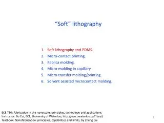
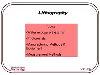
Lithography(controlling width and depth,by using stencils, masks, & templates)
Lithography Nanoscience Rocks! Nanoscience Rocks (Using a stencil or mask)
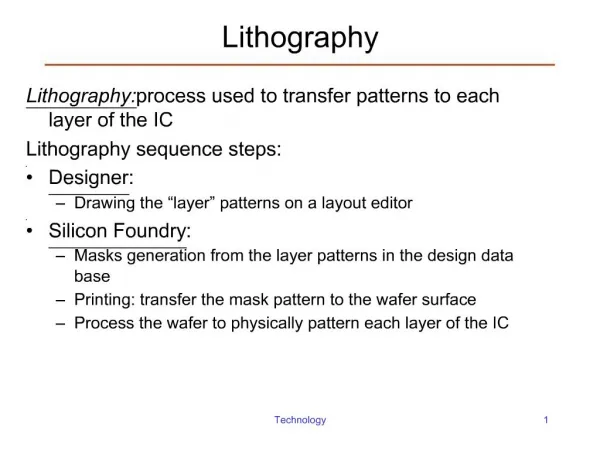
narrow trench • Photolithography • Electron-Beam Lithography • X-ray Lithography • Focused Ion-Beam Lithography • Block Copolymer Lithography • Nano Imprint Lithography • Dip Pen Lithography • Interference Lithography • Contact Lithography • Others Some possible desired features narrow line Lithography: Basic concepts modified substrate
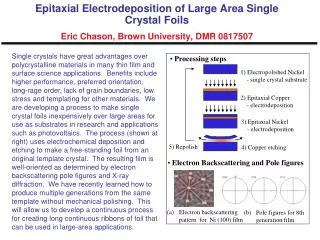
spin coating apply spin bake spin on resist resist expose unexposed exposed mask (reticle) "scission" develop deposit liftoff narrow line process recipe substrate Photolithography for Deposition
Lithography Patterned Several Times IBM Copper Wiring On a Computer Chip
silicon oxide Patterned Oxide substrate silicon spin on resist resist narrow trench expose after mask develop etch lift off lift off Ion implantation Etching dopant ions (e.g., B+, P+) Other Uses
deposit & liftoff deposit & liftoff exposed region results in presence of structure exposed region results in absence of structure (generally poorer resolution) Positive Resist Negative Resist resist resist expose expose cross-linking scission Positive and Negative Resists develop develop
lens Several Types of Lithography contact proximity projection high resolution extends mask life enables "stepping"
How low can you go? minimum linewidth • There are actually many contributing factors that limit the minimum linewidth: • optical diffraction () • resist sensitivity • depth of focus • purity of light source • numerical aperture of lens minimum pitch Resolution Limit of PL
k1 ~ 0.4 - 1.1 (depends on materials, optics and conditions) • is wavelength of light used NA ~ 0.16 - 0.6 is the numerical aperture of the lens system Rayleigh diffraction criterion—> 2bmin = 0.61/NA is part of the underlying reason Resolution in Projection Lithography With careful engineering, R ~/2 can be achieved Contact Lithography z is resist thickness Down to 45 nm
Electron Beam Polymer film Silicon crystal Electron-Beam Lithography Nanoscopic Mask ! Down to 10 nm
Deposition Template Etching Mask Nanoporous Membrane CORE CONCEPT FOR NANOFABRICATION (physical or electrochemical) Remove polymer block within cylinders (expose and develop) Down to 3 nm
Solar Cells Benefit: Sun is an unlimited source of electronic energy. Konarka
“load” + - Electric Solar Cells Made from single-crystal silicon wafers (conventionally) Sunlight wires - cross-sectional view n-type silicon Voltage p-type silicon + Current The load can be a lamp, an electric motor, a CD player, a toaster, etc
“load” Nanostructured Solar Cells Sunlight - Voltage + Current More interface area - More power!
Next.... ....Electrodeposition