Download
1 / 14
140 likes | 284 Views
Shape from Stereo. Disparity between two images Photogrammetry Finding Co rresponding Points Correlation based methods Feature based methods. Introduction. We can see objects in depth by utilizing the difference between the images in our left and right eyes.

E N D
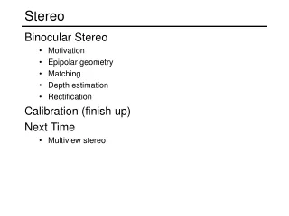
Shape from Stereo Disparity between two images Photogrammetry Finding Corresponding Points Correlation based methods Feature based methods
Introduction • We can see objects in depth by utilizing the difference between the images in our left and right eyes. • Stereo is one of many depth cues, but easiest to understand. • Points on the surfaces of the objects are imaged in different relative positions on their distances from the viewer.
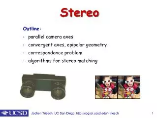
Disparity between the two images • Suppose that we rigidly attach two cameras to each other so that their optical axis are parallel and separated by a distance T. The line connecting the lens centers is called the baseline. • Assume that the baseline is perpendicular to the optical axes and orient the x-axis so that it is parallel to the baseline.
Disparity between the two images • Distance is inversely proportional to disparity. (The distance to near objects can therefore be measured accurately, while that to far objects cannot.) • The disparity is directly proportional to T, the distance between lens centers. (The accuracy of the depth determination increases with increasing baseline T. Unfortunately, as the separation of the cameras increases, the two images become less similar.) • The disparity is also proportional to the effective focal distance f, because the images are magnified as the focal length is increased.
Disparity between the two images • A point in the environment visible from both camera stations gives rise to a pair of image points called a conjugate pair. • Note that a point in the right imagecorresponding to a specified point in the left image must lie somewhere on a particular line, because the two have the same y-coordinate. This line is the epipolar line.
Photogrammetry • In practice, the two cameras used to obtain a stereo pair will not be aligned exactly, as we have assumed so far in our simplified analysis. • It is difficult to arrange for the optical axes to be exactly parallel and for the baseline to be exactly perpendicular to the optical axes. • In fact, if the two cameras are to be exposed to more or less the same collection of objects, they may have to be turned.
Photogrammetry • One of the most important practical applications of the stereo is in photogrammetry. In this field the shape of the surface of an object is determined from overlapping photographs taken by carefully calibrated cameras. • Adjacent pairs of photographs are presented to the left and right eye in a device called a stereo comparator that makes it possible for an observer to accurately measure the disparity of identifiable points on the surface. • We must determine the relation between the camera’s positions and orientation when the exposures were made. This process, called relative orientation, determines the transformation between coordinate systems.
Photogrammetry • Transformation between two camera stations can be treated as a rigid body motion and can be decomposed into a rotation and translation. • If rl=(xl,yl,zl)T is the position of P measured in the left camera coordinate system and rr=(xr,yr,zr)T is the position of the same point measured in the right camera coordinate system, then, rr=Rrl+r0, • Where R is a 3x3 orthonormal matrix representing the rotation and r0 is an offset vector corresponding to the translation. RTR=I where I is the 3x3 identity matrix.
Finding Corresponding Points • We will consider the corresponding point problem to determine which point in one image corresponds to a given point in the other image. • Correlation-based methods • Feature-based methods
Correlation Based Stereo Methods • In the correlation based method, depth is computed at each pixel. • A gray level patch around a pixel in the left image is correlated with the corresponding pixel in the right image. The disparity for the best match is determined.
Algorithm CORR-MATCHING The input is a stereo pair of images Il(left) and Ir (right). Let pl and pr be pixels in the left and right image, 2W+1 the width (in pixel) of the correlation window, R(pl) the search region in the right image associated with pl, and (u,v) a function of two pixel values, u, v. For each pixel pl = [i, j]T of the left image: 1. for each displacement d = [d1,d2]T R(pl) compute 2. the disparity of pl is the vector that maximizes c(d) over R(pl): The output is an array of disparities (the disparity map), one per each pixel of Il.
Two widely adopted choices for the function (u,v) are (u,v)=u.v which yields the cross-correlation between the window in the left image and the search region in the right image, and (u,v)= (u-v)2 which perform the so called SSD (sum of squered distance) or block matching.