Download

1 / 32
330 likes | 498 Views
Model-Specific Registers. A look at Intel’s scheme for introducing new CPU features. Microprocessor evolution…. 8080. 64K-memory, 8-bit registers (no mul/div, no FPU). 1973. 8086. 1M -memory, 16-bit registers, I/O-ports (8087 option). 1978. 80186.

E N D
Model-Specific Registers A look at Intel’s scheme for introducing new CPU features
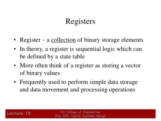
Microprocessor evolution… 8080 64K-memory, 8-bit registers (no mul/div, no FPU) 1973 8086 1M -memory, 16-bit registers, I/O-ports (8087 option) 1978 80186 Ins/outs, shift/rotate-immediate, integrated-DMA+PIC+Timers 1981 80286 16M-memory, protected-mode multitasking (80287 option) 1982 80386 Added TR6, TR7 4GB-memory, 32-bit registers, paging (287/387 options) 1985 80486 Integrated FPU, RISC, cacheing, xadd (APIC option) Added TR3, TR4, TR5 1989 MMX-instructions, integrated local-APIC, MSRs, dual-pipelines, branch-prediction 80586 “Pentium” Removed TR3,TR4,TR5,TR6,TR7 1993
The ‘Model-Specific’ concept • Beginning with the Pentium processor, Intel has been including ‘experimental’ features in its processors, warning that they may disappear from future designs, but providing a standard and permanent way for all such features to be accessed • This access is via a pair of ‘privileged’ instructions (rdmsr and wrmsr) that can only be executed by ‘ring0’ code
Quite a few MSRs now! • At first there were only about a dozen of these MSRs (Model-Specific Registers), but lately their number is well over 200 • Some MSRs have evidently proven to be sufficiently satisfactory and worth having that they are now deemed as permanent fixtures of the defined i386 architecture
The Time-Stamp Counter • This 64-bit Model-Specific Register was introduced in the Pentium processor and has been present in each CPU thereafter • It increments once every CPU clock-cycle, starting from 0 when power is turned on • It won’t overflow for at least ten years • Unprivileged programs (ring3) normally can access, it via the rdtsc instruction
Using the TSC 64-bits 63 32 31 0 EDX EAX time0: .quad 0 # saves starting value from the TSC time1: .quad 0 # saves concluding value from TSC # how you can measure CPU clock-cycles in a code-fragment rdtsc # read the Time-Stamp Counter movl %eax, time0+0 # save least-significant longword movl %edx, time0+4 # save most-significant longword # <Your code-fragment to be measured goes here> rdtsc # read the Time-Stamp Counter movl %eax, time1+0 # save least-significant longword movl %edx, time1+4 # save most-significant longword # now subtract starting-value ‘time0’ from ending value ‘time1’
The TSC as an MSR • Each Model-Specific Register has its own identifying register-number, and it can be accessed (from ring0) using the special pair of instructions: rdmsr and wrmsr • The Time-Stamp Counter is MSR number 0x10 • To write a new 64-bit value into the TSC, you load the desired 64-bit value into the EDX:EAX register-pair, you put the MSR ID-number 0x10 into register ECX, then you execute wrmsr
IA32_APIC_BASE • This register has MSR number 0x1B and is private to each CPU in an SMP system • It establishes the base-address for the Local-APIC’s memory-mapped registers (the default base-address is 0xFEE00000, but that can be changed using this MSR) • The CPU’s Local-APIC functions can be either enabled or disabled (via bit #11) • The BSP can be recognized (via bit #8)
Relocating the APIC registers IA32_APIC_BASE (64-bits) 63 32 31 12 11 8 0 reserved APIC base-address (4K page-number) E N B S P Default-value for APIC base-address page = 0xFEE00 Local-APIC Enable bit (1=enabled, 0=disabled) Boot-Strap Processor (read-only): 1=yes, 0=no # make the processor’s Local-APIC registers accessible in real-mode mov $0x000D8000, %eax # least-significant 32-bits mov $0x00000000, %edx # most-significant 32-bits mov $0x1B, %ecx # MSR register-number wrmsr # write to specified MSR
Extended Feature Enable Register • This Model-Specific Register (MSR) was introduced in the AMD64 architecture and perpetuated by EM64T (for compatibility) 63 11 10 8 0 N X E L M A L M E S C E Legend: SCE = SysCall/sysret is Enabled (1=yes, 0=no) LME = Long-Mode is Enabled (1=yes, 0=no) LMA = Long-Mode is Active (1=yes, 0=no) NXE = Non-eXecutable pages Enabled (1=yes, 0=no) NOTE: The MSR address-index for EFER = 0xC0000080, and this register is accessed using RDMSR or WRMSR instructions
The x86 operating ‘modes’ Virtual 8086 mode IA-32e mode 64-bit mode Power on Real mode Protected mode Compatibility mode System Management mode
Why CPU’s ‘mode’ matters • Key differences among the x86 modes: • How memory is addressed and mapped • What instruction-set is available • Which registers are accessible • Which ‘exceptions’ may be generated • What data-structures are required • How task-switching can be accomplished • How interrupts will be processed
Mode transitions • The processor starts up in ‘real mode’ • Mode-transitions normally happen under program control (except for transitions to the so-called ‘System Management Mode’) • Details of programming a mode-change depend on which modes are involved • Some mode-transfers aren’t possible • ‘64-bit mode’ offers a lot of surprises
Registers in 64-bit mode EAX RAX ECX RCX EDX RDX EBX RBX ESP RSP EBP RBP ESI RSI EDI RDI EIP RIP EFLAGS RFLAGS CR0 CR2 CR3 CR4 DR0 DR1 DR2 DR3 DR6 DR7 R8 R9 R10 R11 R12 R13 R14 R15 CR8 63 32 31 16 15 8 7 0 RAX EAX AX AL
Some missing features… • Memory-segmentation is “turned off” • Base-address is zero for CS, DS, ES, SS • Segment-limit checking is not performed • Certain familiar instructions no longer are defined while executing in ’64-bit-mode’ • Cannot use ‘pusha’ and ‘popa’ • Cannot ‘ljmp’ or ‘lcall’ with ‘direct’ addressing • Cannot use ‘lahf’ and ‘sahf’
“canonical” addresses 00000 00001 00010 00011 00100 00101 00110 00111 01000 01001 01010 01011 01100 01101 01110 01111 10000 10001 10010 10011 10100 10101 10110 10111 11000 11001 11010 11011 11100 11101 11110 11111 0xFFFFFFFFFFFFFFFF … 0xFFFF800000000000 “non-canonical” (invalid) virtual addresses “canonical” addresses Analogy using 5-bit values 64-bit “vrtual” address space 0x00007FFFFFFFFFFF … 0x0000000000000000 “canonical” addresses
4-Levels of mapping 63 48 47 39 38 30 29 21 20 12 11 0 sign-extension PML4 PDPT PDIR PTBL offset Page Frame (4KB) 64-bit ‘canonical’ virtual address Page Table Page Directory Page Directory Pointer Table Page Map Level-4 Table CR3 Each mapping-table contains up to 512 quadword-size entries
4-level address-translation • The CPU examines any virtual address it encounters, subdividing it into five fields 63 48 47 39 38 30 29 21 20 12 11 0 sign- extension index into level 4 page-map table index into page- directory pointer table index into page- directory index into page-table offset into page-frame 16-bits 9-bits 9-bits 9-bits 9-bits 12-bits Any 48-bit virtual-address is sign-extended to a 64-bit “canonical” address Only “canonical” 64-bit virtual-addresses are legal in 64-bit mode
Format of 64-bit table-entries Physical addresses on our current Core-2 CPUs are only 40 bits 63 62 52 51 40 39 32 E X B avl Reserved (must be 0) Page-frame physical base-address [39..32] 31 12 11 9 8 7 6 5 4 3 2 1 0 Page-frame physical base-address[31..12] avl A P C D P W T U W P Meaning of these bits varies with the table Legend: P = Present (1=yes, 0=no) PWT = Page Cache Disable (1=yes, 0=no) W = Writable (1=yes, 0=no) PWT = Page Write-Through (1=yes, 0=no) U = User-page (1=yes, 0=no) avl = available for user-defined purposes A = Accessed (1=yes, 0=no) EXB = Execution-disabled Bit (if EFER.NXE=1)
RDMSR and WRMSR • An assembly language code-fragment to turn on the LME-bit (‘Long-Mode’ Enable): # Each Model-Specific Register (MSR) is 64-bits wide and has a unique # 32-bit address-index which is first placed into register ECX. Then the # least-significant 32-bits of that MSR is accessed using register EAX, # while the most-significant 32-bits is accessed using register EDX. mov $0xC0000080, %ecx # setup EFER address-index rdmsr # read EFER into (EDX,EAX) bts $8, %eax # set the LME-bit’s image to 1 wrmsr # write (EDX,EAX) into EFER # NOTE: RDMSR and WRMSR must be executed at ‘Ring0’ privilege-level.
Control Registers CR4 and CR0 31 13 5 0 0 0 0 0 0 0 0 0 0 0 0 0 0 0 0 0 0 0 V M X E 0 0 O S X M M E x O S F X C R P C E P G E M C E P A E P S E D E T S D P V I V M E Control Register CR4 31 0 P G C D N W 0 0 0 0 0 0 0 0 0 0 A M 0 W P 0 0 0 0 0 0 0 0 0 0 N E E T T S E M M P P E Control Register CR0 Legend (for 64-bit mode): PE = Protected-mode Enabled (1=yes, 0=no) PG = Paging Enabled (1=yes, 0=no) PAE = Page-Addressing Extensions (1=enabled, 0=disabled)
Segment-Descriptor Format 64-bit code-segment (‘LONG’ mode) 63 32 Base[31..24] (if L=0) G D L A V L Limit [19..16] (if L=0) P D P L S X C / D R / W A Base[23..16] (if L=0) Base[15..0] (if L=0) Limit[15..0] (if L=0) 31 0 Legend:DPL = Descriptor Privilege Level (0..3) G = Granularity (0 = byte, 1 = 4KB-page) P = Present (0 = no, 1 = yes) D = Default size (0 = 16-bit, 1 = 32-bit) S = System (0 = yes, 1 = no) X = eXecutable (0 = no, 1 = yes) A = Accessed (0 = no, 1 = yes) code-segments: R = Readable (0 = no, 1 = yes) C = Conforming (0=no, 1=yes) data-segments: W = Writable (0 = no, 1 = yes) D = expands-Down (0=no, 1=yes) L = Long-mode (i.e., 64-bit addressing) (0=no, 1=yes) AVL = Available for user’s purposes
IA-32e Call-Gate descriptor 127 96 Reserved (must be 0) offset[63..32] offset[63..32] offset[31..16] Base[31..24] (if S=0) G D L A V L P D P L 0 X Gate Type (=1100) C / D R / W Reserved (must be 0) code-segment selector offset[15..0] 31 0 We can use a call-gate to ‘jump’ from 16-bit code-segment to a 64-bit code-segment
Summary of steps • Transition from real-mode to IA-32e mode: • Build the table of global descriptors • Load GDTR with pseudo-descriptor for GDT • Build the 4-level page-mapping tables • Enable IA-32e mode (set EFER.LME=1) • Enable Page-Address Extensions (CR4.PAE) • Load Level4 page-map table address in CR3 • Activate IA-32e mode (CR0.PE and CR0.PG) • Transfer via call-gate to 64-bit code-segment
Notes on the transition • Code-segment must be “identity-mapped” • Interrupts have to be temporarily disabled • All memory-addressing in 64-bit mode via CS, SS, DS or ES uses 0 as base-address (and checking of segment-limits is omitted)
For a return to ‘real-mode’ • Processor must enter 16-bit code-segment in ‘compatibility-mode’ via indirect far jump • Load segment-registers DS, ES, and SS with ‘writable’ 16-bit segment-selectors (64K-limit) • Code-segment has to be “identity-mapped” • Deactivate IA-32e mode by clearing PG-bit • Leave ‘protected-mode’ by clearing PE-bit • Reload registers CS and SS with real-mode segment-addresses before enabling interrupts
In-class exercise #1 • Try running our ‘trymoves.s’ demo, to see the effect of changing the bottom-half of a 64-bit register • Then modify the instructions in this demo so that you use as many of the new CPU registers as possible (i.e., use R8,…,R15 instead of RAX, RBX, etc., and R8L, R9L, …, instead of AL, BL, etc.)
Demo-program: ‘try64bit.s’ • We created a demo-program that starts in ‘real-mode’, enters 64-bit mode and draws a message, jumps to ‘compatibility mode’ and draws another message, then returns to real-mode and shows a final message • It has to write directly to VRAM when it’s not executing in real-mode – because the ROM-BIOS routines use ‘real’-style code
How text-mode VRAM works • The video memory resides at 0x000B8000 and in text-mode it is organized as a linear array of two-byte elements (i.e., ‘words’): • Array-elements are arranged in “row-major” order (left-to-right, top-to-bottom) 15 8 7 0 Attribute-code for the foreground and background colors Ascii code for character
Default color-programming 7 6 5 4 3 2 1 0 Blinking 0 Red 0 Green 0 Blue 1 Intense 1 Red 1 Green 1 Blue 1 BACKCOLOR FORECOLOR
Character-cell screen-locations 80 cells-per-row 25 rows for (row 0, column 0) the address-offset is (0*80+0)*2 for (row 2, column 79) the address-offset is (2*80+79)*2 for (row 24, column 40) the address-offset is (24*80+40)*2
In-class exercise #2 • Can you modify the message-colors used in our ‘try64bit.s’ demo-program so that: • the first message is bright-red against white • the second message is brown against cyan • The final message is magenta against black