Machine Model Pseudo-Registers Graph Coloring
This overview discusses the principles of register allocation in compiler design, focusing on the machine model that governs operations with registers. It explains the use of pseudo-registers and their impact on allocation techniques. The text addresses the challenges of spilling pseudo-registers when physical registers are insufficient and introduces interference graphs for managing conflicts between pseudo-registers. Finally, the recursive coloring algorithm is described as a method for efficient register assignment, providing a practical approach to achieving k-colorability in register allocation.

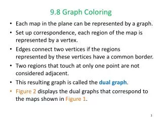
Machine Model Pseudo-Registers Graph Coloring
E N D
Presentation Transcript
Register Allocation Note: Some slides “borrowed” from Wei Li Machine ModelPseudo-RegistersGraph Coloring Jeffrey D. Ullman Stanford University
Registers • Assume some large but finite number of registers are available to hold values. • All operations take place in registers. • Load and Store operations copy values between registers and memory. • Move copies values between two registers.
The Machine Model • Instructions of the form (Op Destination, Source(s)). • Examples: • Load r1, x • Copy memory location x into register r1. • Store y, r2 • Copy register 2 into memory location y. • Add r3, r4, r5 • Add the contents of registers r4 and r5 and put the result in register r3.
Memory Locations Memory locations are either: • Static (fixed address). • Stack (in the activation record for a function). • Heap (shared memory for objects).
Address Modes • 100(r1) = 100 + contents(r1) • Useful if r1 holds the first address of a heap object or activation record and we want the field or variable offset by 100 from that address. • *100(r1) = contents(100 + contents(r1)) • #100 = literal 100 • Example: Load r1, #100 puts the value 100 into register r1.
Translating 3-Address Code to Machine Code • Example (static addresses): x = y + z becomes Load r1, y Load r2, z Add r3, r1, r2 Store x, r3 • Use indirect address modes if x, y, and/or z are allocated on stack or heap.
Pseudo-Registers • Think of each variable x in the three-address code (“quads”) as a pseudo-register. • That is, x will be allocated some physical register when it is operated upon. • When not operated upon, the value of x may be in a register or x’s memory location, or both. • Benefit: Lets us think in terms of intermediate-code steps rather than machine-level instructions.
Spilling Psuedo-Registers • When there are not enough physical registers to hold all pseudo-registers, the compiler must select some pseudo-registers to spill (store in memory). • Must keep some registers exclusively for operating on spilled pseudo-registers. • Choose which to spill judiciously: • Longest time to next use? • Spill variables used only in outer loops?
Interference of Pseudo-Registers • Two pseudo-registers interfere if they cannot be assigned the same physical register. • Reason: at some point in the program, both are live. • Interference graph: • Nodes = pseudo-registers. • Edge between two nodes if their pseudo-registers interfere.
Example: Basic Block a = 1 b = 2 c = a + b d = a + 3 e = a + b t1 = 1 t2 = 2 t3 = t1 + t2 t4 = t1 + 3 t5 = t1 + t2 As intermediate code As pseudo-registers Assume no variables live on exit.
Interference Graph t1 = 1 t2 = 2 t3 = t1 + t2 t4 = t1 + 3 t5 = t1 + t2 t2 t1 t3 Scope of t1 interferes with all but t5 t5 t4
Interference Graph t1 = 1 t2 = 2 t3 = t1 + t2 t4 = t1 + 3 t5 = t1 + t2 t2 t1 t3 Scope of t3 interferes with only t1 and t2 t5 t4
Register Allocation by Coloring • A graph is k-colorableiff we can assign one of k colors to each node in such a way that no edge has both ends colored the same color. • We can use k registers to assign physical registers to pseudo-registers iff the interference graph is k-colorable. • Unfortunately, k-colorability is NP-complete, and even approximation is NP-complete. • But a simple algorithm does pretty well in practice.
Recursive Coloring Algorithm • Tries to find a k-coloring of a graph. • Find a node n with fewer than k neighbors. • If no such node, we are OK if only one node remains; color it any color. • Otherwise we are hosed and need to do exhaustive search or increase k. • Remove n and all edges attached to n. • Recursively color the remaining graph with k colors. • Restore node n and color it with a color not used for any of its neighbors.
Colorable by 3 Colors? t2 t1 = 1 t2 = 2 t3 = t1 + t2 t4 = t1 + 3 t5 = t1 + t2 t1 t3 t5 t4
Colorable by 3 Colors? t2 Pick t5 and remove its edges t1 t3 t4
Colorable by 3 Colors? t2 Pick t4 and remove its edges t1 t3
Colorable by 3 Colors? t2 Pick t3 and remove its edges t1
Colorable by 3 Colors? Pick t2 and remove its edges t1
Register Assignment • Reverse process, starting with any color for last node t1/r1
Register Assignment • Color t2 t2/r2 t1/r1
Register Assignment • Color t3 t2/r2 t1/r1 t3/r3
Register Assignment • Color t4 t2/r2 t1/r1 t3/r3 t4/r3
Register Assignment • Color t5 t2/r2 t1/r1 t3/r3 t5/r1 t4/r3
After Register Allocation r1 = 1 r2 = 2 r3 = r1 + r2 r3 = r1 + 3 r1 = r1 + r2 t1 = 1 t2 = 2 t3 = t1 + t2 t4 = t1 + 3 t5 = t1 + t2