Electrical Circuit Fundamentals and Ohm's Law Explained
Understand fundamental electrical circuit principles, including Ohm's Law, Joule's Law, and resistance calculations. Learn about current flow in conductors and basic circuit analysis methods.

Electrical Circuit Fundamentals and Ohm's Law Explained
E N D
Presentation Transcript
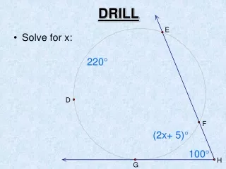
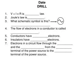
DateDRILL • V = I x R is _________ law. • Joule’s law is___________. • What schematic symbol is this? _________________________ • The flow of electrons in a conductor is called __________________. • Conductors have __________electrons. • Insulators have ___________electrons. • Electrons in a circuit flow through the __________ and the _______________ from the __________ terminal of the power source to the ___________ terminal of the power source.
DateDRILL • V = I x R is __Ohm’s_______ law. • Joule’s law is _ P = V x I _____. • What schematic symbol is this? _AC Power Source_____________ • The flow of electrons in a conductor is called __Current_________. • Conductors have __free____electrons. • Insulators have __bound____electrons. • Electrons in a circuit flow through the Conductor and the ___Load________ from the negative__ terminal of the power source to the positive terminal of the power source.
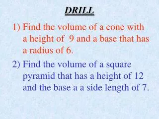
U3e-L3 Resistance Calculations • Calculate the resistance in the following circuit: 100 Ω 100 Ω 100 Ω R3= R2= R1=
1/RT = 1/R1 + 1/R2 + 1/R3 1/RT = 1/100 Ω + 1/100 Ω + 1/100 Ω 1/RT = .01 Ω + .01 Ω + .01 Ω 1/RT = .03 Ω 1 = .03 Ωx RT 1/.03 Ω= RT 33.333 Ω= RT
Draw a schematic for this circuit 25Ω 5Ω 4Ω 10Ω 120v 3Ω 2Ω
R6= 25Ω R3= 5Ω 120v R5= 4Ω R4= 10Ω R2= 2Ω R1= 3Ω
1. Calculate the RT 2. Calculate the Current 3. Calculate the Power
Start by identifying • any parallel segments A R6= 25Ω R3= 5Ω 120v R5= 4Ω R4= 10Ω R2= 2Ω R1= 3Ω
1a. Calculate parallel segments 1/RA = 1/R3 + 1/R4 + 1/R5 1/RA = 1/5 Ω + 1/10 Ω + 1/4 Ω 1/RA = .2 Ω + .1 Ω + .25 Ω 1/RA = .55 Ω 1 = RA x .55 Ω 1/.55 Ω= RA 1.818 Ω= RA
1b. Calculate Total Resistance (RT) RT = R1 + R2 + RA + R6 RT = 3Ω+ 2Ω+ 1.818Ω+ 25Ω RT = 31.818Ω • Calculate Current V = I x R 120v = I x 3.818Ω 120v/3.818Ω= I 31.43 amps. = I
Calculate Power P = V x I P = 120 v x 31.43 amps. P = 3771.6 W
HOMEWORK 120v 10 amps. • Schematic • Resistance = ? • Power = ?
HOMEWORK • What type of power supply (AC or DC)? ___________ • 2. What is the voltage? _____________ • 3. What is the frequency? ___________ Hz. 100 v 50 v 0 v -50 v -100 v 0.3 sec 0.2 sec 0.1 sec