Download
1 / 43
430 likes | 578 Views
DVC 3.34 Produce working drawings to communicate production details for a complex design. Lesley Pearce Team Solutions The Auckland University Nov 2012. Level 3 step ups. Working drawings are to communicate design details that will allow its manufacturing or construction.

E N D
DVC 3.34 Produce working drawings to communicate production details for a complex design Lesley Pearce Team Solutions The Auckland University Nov 2012
Level 3 step ups • Working drawings are to communicate design details that will allow its manufacturing or construction. • A suitable level of detail for key aspects of the design (depending on complexity and scale of design it is not expected to be done at a comprehensive level)
Key Messages • At level 8: Students develop an understanding about how to communicate a set of related 2D, 3D or 4D working drawings/models that show a suitable level of detailing for a key aspect of design that allow construction and assembly of the complex design.
Teacher guidanceTo support students to develop the skills and knowledge at level 8, teachers could: • Teach this as a stand-alone unit where students are required to interpret design details from a design idea. Or allow students to develop these working drawings from an integrated unit from either product or spatial design. Students must be allowed to decide on the views and production details so this cannot be a class exercise. • Ensure student’s designs have multi-components.
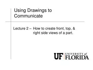
Show students a variety of working drawings that allow a design to be constructed/modelled; architectural plans, engineering plans, animations, traditional and computer generated, 2D, 3D and 4D. This will allow them to select a set of drawings to suit their designs. (Third angle orthographic, paraline drawings, perspective drawings, exploded views, isometric, mechanical perspective etc)
A set of related drawings could be of different scales, different views, 2D, 3D, animations that all communicate one design outcome • Allow students to use both 2D and 3D modes to communicate their design outcome. • 4D refers to animations, motion graphics design
Show students the complexity required at this level. It is important there is enough suitable level of detailing (it does not have to be done at a comprehensive level though) • Teach students the correct conventions; line types, construction lines, outlines, section lines, drawing and text layout, dimensioning Plus the conventions used by engineers and architects
Invest in computer software. • Purchase high GSM paper, good pencils and clean instrumental equipment.
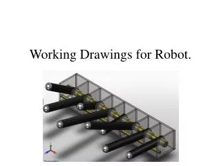
Activity • Using the Achievement Standard would the following drawing meet the level 3 standard? • If not why?
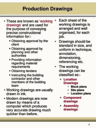
Working drawings • Working drawings are specialized engineering drawings that provide information required to make the part or assembly of the final design. • Working drawings rely on orthographic projection and many other graphical techniques to communicate design information for production.
Definition • The drawings from which a design is built
Assembly drawings maybe pictorial drawings or orthographic drawings • An assembly drawing shows how each part of a design is put together
Parts list • Consists of an itemized list of all the parts to assemble one complete unit • Contains the following: • (1) part number • (2) part name • (3) number of parts req’d • (4) material • (5) description
Set of related 2D, 3D and/or 4D drawings and models • That show interior and exterior details of the components and information related to the construction and assembly of the complex design • The details to be decided by the student
Complex design • Spatial or product design with multiple components
Summary • A Working Drawing has the following usual components:An Isometric Drawing showing the Part Numbers (or Part Labels). • An Exploded View (or Assembly Drawing) showing where the parts go and their fixtures. • An Orthographic Projection(Third Angle) showing the overall and necessary minor dimensions. • If you can afford space for Part Drawings or useful Sectional Views to be included, go ahead and do so. Otherwise you must at least have those in of your development phase. Just think about the part drawings as a summary of your conclusions on the physical product project. Showing all the details, positions, trim lines and dimensions. (Note: Production Sequences and a Gantt Chart Production Plan need not be present in your presentation boards, however they MUST be included at the end of your development phase. • A Material List showing all the Part Numbers, the Materials used, the Dimensions and the respective Quantities.
Some Tips and Pointers:Isometric Drawings: If the product has several components, especially those with components within each bigger component, you may consider drawing those components and label them seperately. It is impossible to draw all of them within (with lots of hidden lines) and attempt to number them off. That will be VERY messy and impossible to read. Finish off with a neat Exploded Drawing to show how each components come together. • Exploded Views: As long as the parts are aligned consistently (Isometric or Oblique) your exploded view should look neat. Not all parts can be aligned straight to its connection point. In this case you can draw your component slightly off, but use lines to create a 'path' to lead it to the connection point. The example above has everything aligned. For an 'off' example click here. In the linked example you will find a dowel that is not aligned. • Orthographic Projection: Leader lines should not touch the main drawing and should have a lighter line weight than the object. A good guide would be at least 10mm away from the drawn object. Spacing between dimension lines to the next should be consistent. A good guide would be at least 5mm away from the drawn object. Dimensions are usually written 'on' the dimension line. For vertical dimension lines, the dimensions are usually written on the left of the line following the orientation of the line. • Material List: Most common mistake is the written dimension. Length = the longest or the largest dimension. Followed by Width and the smallest dimension is the Thickness. It is worthy to note that numbering in the material list goes from '1' from the base up.
Students can: • Produce a set of related drawings that can utilize two dimensional and three dimensional modes instrumentally constructed/modelled using either traditional drafting equipment or computer applications. • Use digital animations to support the related drawings. • Related drawings show information which allows construction and assembly of a multi-component design
Select the views and modes (traditional methods or computer applications) that suits the accepted practice and conventions for the design context • Communicate the design details of either a spatial or product design to a level that will allow the design to be manufactured or constructed • Show exterior and interior details that would allow production of key aspects of the details of the design outcome
Use the correct conventions for either an engineering or architectural drawings • Apply drawing techniques with accuracy and precision • Select views and modes as suitable and accepted as practice and conventions
Assessment Specifications • Students are required to select key aspects of their designs, the views, modes to produce a set of related drawings. • Depending on the complexity of the design and scale of the design, this is not necessarily expected to be done to a comprehensive extent, provided there is suitable level of detailing shown for a key aspect of the design. • Candidates may use any computer applications. For the production of working drawings (e.g. Vectorworks, Solidworks, Archicad, Revit, etc) though animations can be used as supporting evidence.
Digital animations can be used to support the related drawings to help communicate interior and exterior information related to the construction and assembly of a multi component design.