Download
1 / 27
290 likes | 617 Views
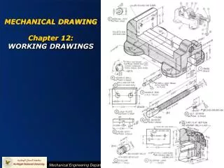
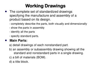
Working Drawings. The complete set of standardized drawings specifying the manufacture and assembly of a product based on its design. - completely describe the parts, both visually and dimensionally - show the parts in assembly - identify all the parts - specify standard parts. Main Parts:

E N D
Working Drawings • The complete set of standardized drawings specifying the manufacture and assembly of a product based on its design. - completely describe the parts, both visually and dimensionally - show the parts in assembly - identify all the parts - specify standard parts. • Main Parts: a) detail drawings of each nonstandard part. b) an assembly or subassembly drawing showing all the standard and nonstandard parts in a single drawing. c) a bill of materials (BOM). d) a title block.
Detail Drawing • a dimensioned, multiview drawing of a single part, describing the part’s shape, size, material, and finish, in sufficient detail for the part to be manufactured based on the drawing alone. • Show all necessary dimensioned views needed to make the part. • Indicate material and tolerances. • Indicate any finish treatments (plating, etc.) and requirements for surface-finish roughness. • Standard parts are not drawn as details because they are normally purchased, not manufactured, for design. • It is often preferred to show just one part per sheet so the same part drawing can be included in multiple assemblies without confusion. • When more than one detail is placed on a sheet, the spacing between details is carefully planned, including leaving sufficient room for dimensions and notes.
Assembly Drawings • shows how each part of a design is put together. • If the design depicted is only part of the total assembly, it is referred to as a subassembly. • Not usually dimensioned unless here are dimensions that are critical to maintain during assembly. • Hidden lines not usually needed. • Types: • Outline assembly gives a general graphic description of the exterior shape. (simple assemblies only) • Sectioned assembly gives a general graphic description of the interior shape by passing a cutting plane through all or part of the assembly. (for complicated assemblies) • Pictorial assembly gives a general graphic description of each part, and uses center lines to show how the parts are assembled. (3-D CAD model in pictorial view)
Sectioned Assembly • Different hatch patterns indicate which part is which in the assembly section. • The material for the part can be identified by different hatch patterns. • The hatch patterns run at different angles on different parts in the assembly
Thin Parts Filled In Black • Thin parts like the gasket shown here are too small to hatch. • Parts like these are filled in solidly with black.
Parts Lists (Bill of Materials) • For each part: show part name, item number, material, and quantity needed for the assembly. • For standard parts, include the catalog number, and the company part number. • Parts List may be on a separate document • Identifying Part on drawing • Leader lines with balloons, assigning each part a detail number, in sequential order and keyed to the list of parts in the parts list. • Part No. may be Placed Directly on Drawing
Title blocks • Used to record all the important information necessary for the working drawings. • The title block is normally located in the lower right corner of the drawing sheet. • Almost All Engineering Firms Have Some Standard/Default Elements That are Included in all Engineering Drawings • Title blocks should contain the following: • Name and address of the company or design activity. • Title of the drawing. • Drawing number. • Names and dates of the drafters, checker, issue date, contract number, etc. • Predominant drawing scale. • Drawing sheet size letter designation. • Actual or estimated weight of the item. • Sheet number, if there are multiple sheets
Drawing SCALES • Typical Scale Callout SCALE 1:16 Length On DRAWING Length in REAL WORLD • Example: Scale: 1:2000 20 mm in drawing length In REAL WORLD = 40 km
Architect/CE Scale • Recall Scale Definition Size on DRAWING Size in REAL WORLD • Example - Given Scale: 2” = 5’-0”
1st and 3rd Angle Projections • THIRD Angle Projection - customarily used in the US. The front view is below the top, and to the left of the right-side view. • FIRST Angle Projection – used in Europe; essentially projects the “shadow” of an object onto a screen behind it. The top view is below the front view and the right-side view is to the left of the front view. • The projection used in the drawing should be indicated in the title block.
FIRST Angle Proj THIRD Angle Proj Projection used in drawing is indicated in Title Block.
Threaded Fasteners • Fastening is a method of connecting or joining two or more parts together, using processes or devices. • Threaded Fasteners use cylindrical surfaces with mating helical cuts Helical Threads Have Three Main Applications - Used to HOLD parts together • Used to ADJUST the Position of parts with reference to one another • - Used to TRANSMIT Power
Unified (USA) Thread Series • The Unified System (UN) Adopted on 18-Nov-1948 by the USA, UK , & Canada • Made fasteners Interchangeable • The UN Designation (Spec) has Two Main Elements • The Major (outside) Diameter • Specified by Either • A size No. running from 0-12 (0.06-0.216 inches) • The Major Dia, in Fractional inches (¼-4 inches) • The Inverse Pitch in Threads per Inch
UN Thread Series – 6 Total • COARSE Series (UNC or NC) • For General Use Where Rapid Assembly is Required • Threads Engage, or “Start” Easily • FINE Series (UNF or NF) • For Applications Requiring Greater Strength or Where the Length of Engagement is Limited • Used Extensively in Aircraft and Automobile Manufacturing
UN Thread Series – cont • EXTRA FINE Series (UNEF or NEF) • For Highly Stressed Parts • 8N Series (8N) • A Substitute for Coarse-Thread Series for Diameters larger Than 1” • All diameters have 8 threads per inch. Often Used on bolts for high pressure pipe applications.
UN Thread Series – cont.2 • 12N Series (12 UN or 12N) • A Continuation of the Fine-Thread Series for Diameters Larger than 1.5” • All diameters have 12 thds/in. Used in boiler work and in Machine Construction. • 16N Series (16 UN or 16N) • A Continuation of the ExtraFine-Thread Series for Diameters Larger than 2” • All diameters have 16 thds/in. Used on adjusting collars and other applications where thread must have fine adjustment regardless of diameter.
Screw Fastener Specification • Defaults That Need NOT be Part of Callout • NC or NF implied by Diameter & TPI • Class → Default is 2A or 2B • Hand → Default is RIGHT
UN Thread Classes • Two Types of Classes • Refers to EXTERNAL Threads (Bolts & Screws) • Refers to INTERNAL Threads (Nuts & “Tapped” holes) • Class Descriptions • Provide Liberal Allowance for Ease of Assembly Even When Threads are Dirty or Slightly Damaged • Not Commonly Used
UN Thread Classes cont • Class Descriptions cont. • For Commercially Produced bolts, screws, nuts, and other threaded fasteners • By Far the Most Common • Used in Precision Assemblies where a Close Fit is Required to WithStand Stress & Vibration • Typical Use is Aircraft or other Hi-Vibration Applications
Metric Thread Specification • Note That Pitch is Stated Explicitly • Compares to Inverse Pitch (TPI) for Unified Specification
Detailed Thread Representation • Used when diameter of thread is 1” or larger on plotted or Hand drawing. • Use ONLY When It is Important to Show the Function of the Thread • Not Typical for Hand Drawings
Simplified & Schematic Forms • Imply depth of thread with hidden lines for simplified representation • Use alternating LONG THIN & SHORT THICK lines to represent ROOT & CREST lines in schematic representation • Spacing is SCHEMATIC; need not Match Actual Pitch
Representation Comparison • Detailed → very tedious to construct • Not commonly used on Engineering Drawings • Simplified → fast but potentially confusing • Hidden lines can be mistaken for Object Features • Schematic → best overall • Fast, yet clearly shows the threads