Download
1 / 17
170 likes | 324 Views
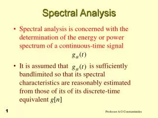
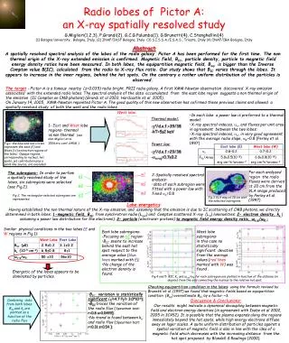
Spatially Resolved Spectral Analysis of Gradual Hardening Flare. Takasaki H. , Kiyohara J. (Kyoto Univ.), Asai A., Nakajima H. (NRO) , Yokoyama T. (Univ. of Tokyo), Sato J. ( STEL/Nagoya-U.), Kosugi T. (JAXA). Oct, 27, 2004 Nobeyama. Introduction.

E N D
Spatially Resolved Spectral Analysis of Gradual Hardening Flare Takasaki H. , Kiyohara J. (Kyoto Univ.), Asai A., Nakajima H. (NRO) , Yokoyama T. (Univ. of Tokyo), Sato J. ( STEL/Nagoya-U.), Kosugi T. (JAXA) Oct, 27, 2004 Nobeyama
Introduction gradual hardening flares (Kosugi et al. 1985) • long duration event and gradual variation in the HXR and microwave fluxes. • HXR emission with a spectrum that systematically hardens with time (the power-law spectral index is reaching ≦ 3) • the energy dependence time delay of microwave and HXR peak Tsuneta et al. (1984) reported that the gradual hardening HXR source located on apex of coronal loop. It is suggested that the magnetic trapping of energetic electrons plays significant role in this type of flares!!! Really??
How is gradual hard flare seen in microwave? • Light Curve • HXR time profile ~ microwave time profile • one-to-one correspondence of individual spikes between HXR and microwave in their time profiles • HXR and microwave are generated by a single population of energetic electrons accelerated in the flare energy-release process.
N E Spectral δHXR≠δMicrowave There is a breakup in the energy spectrum of the electrons. Implies “not single population” !!!? However, previous works (of the light curves / of the spectral) are performed without spatial resolution. “spatially resolved” spectral distribution (imaging spectroscopy) is needed. NoRH + HXT : use images in both wavelengths
Data Nov. 25, 2000 01:21(UT) GOES class M8.2 GOES Yohkoh/HXT
This is calculated by M2 and H-band temporal variation of spectral index NOT imaging spectroscopy In HXR, a soft-hard-harder temporal variation of electron spectral index. Temporal behavior and value of microwave spectral index is different from those of HXR. This is calculated by 1, 2, 3.75, 9.4, 17, 34 GHz NOT imaging spectroscopy
±0 ±0 ±0 +2 +4 ±0 +4 +8 +2 Energy dependence of HXR time profiles L-band (14-23 keV) M1-band (23-33keV) M2-band (33-53 keV) H-band (53-93 keV) Time delay of HXR peak emission • energy dependence of particle trapping (Coulomb collision) τ= 9.5×10⁷ E1.5/ N (Spitzer, Physics of Fully Ionized Gases) In this flare, HXR is emitted from precipitating electrons which are once trapped in coronal loops!
NoRH (34GHz) EIT (195 Å) Nov. 25, 2000 01:21(UT) GOES class M8.2
Identification of hardening HXR source Hard X-ray contour on Ha image HXR is emitted at footpoint. the dominant hard X-ray source appears as a single source located above the Habright point in eastern-ribbon and the temporal and spatial variation of this HXR source is correspond with the variation of this Habright point.
34 GHz microwave emission For the impulsive phase of each peak, the microwave emission from the western footpoint was considerably larger than that from the looptop. After peak, on the contrary, the emission of loop top is larger than that of footpoint.
→trapping component Spatial distribution of microwave sources at valleys of time profile at peaks of time profile microwave is dominantly emitted at western footpoint. microwave is dominantly emitted at looptop. →direct precipitation component →precipitation after trap component →Mirroring component In the microwave, we can also see the trapped component.
Brief summary of flare configuration Microwave × HXR -70 gauss HXR +800 gauss trapped electrons -70 Gauss + 800 Gauss SoHO/MDI Ha ribbon
Spatially resolved spectral index (footpoint) Electron spectral index (HXR) δHXR A δrectangleA Electron spectral index (Microwave) Total emission (from rectangle A) NoRH (17GHz) ※HXR is emitted at only rectangle C Total emission (from rectangle C) HXR; δ=γ+1.0(thick target) Microwave; δ=(1.22 – α)/0.9 (Dulk, 1985)
Spectral indeces of microwave (A) and HXR (C) show quit similar evolution. • Single population at footpoint emission!!!? • Both are mainly once-trapped electrons. A C B • There is a constant gap between δMicrowave and δHXR ; (δHXR-δMicrowave~2). • NOT single power-law!!?? • … depends on theoretical or not??? Peak times of microwave (A) delay for ~15 sec from those of HXR (C).
Spatially resolved spectral index (looptop) Electron spectral index (HXR) δHXR δmicrowave C Electron spectral index (Microwave) B NoRH (17GHz) Total emission (rectangle B) ※HXR is emitted at only rectangle C Total emission (rectangle C) HXR; δ=γ+1.0 (thick target) Microwave; δ=(1.22 – α)/0.9 (Dulk, 1985)
Spectral indeces of microwave (B) and HXR (C) show quit different evolution. • different from footpoint population. C B • Peak time of microwave (B) delay for ~30 sec. from those of HXR (C). • The energy of electrons which produce microwave emission at looptop are larger than those at the footpoint if we assume the Coulomb collision.
Summary • We performed imaging spectroscopy on a gradual hardening flare. • Electrons which produce HXR and microwave at footpoint are probably produced by same population, • But, there is a gap which we can not explain … • They mainly precipitate after trapping. • The energy of electron in looptop may be larger than that in footpoint, and these electrons may be strongly trapped.