Gesture Controlled Car (GCC)
Gesture Controlled Car (GCC). By: Ashwaq Alkailany Reema Abubaker Supervised by: Dr. Luia Malhis. Introduction Introduction. Goal. Outline. Hardware . How Gesture Controlled Car Work?. Problems and solutions. Future work and conclusion. Introduction.

Gesture Controlled Car (GCC)
E N D
Presentation Transcript
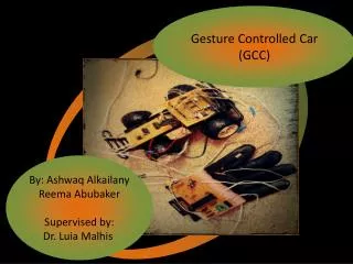
Gesture Controlled Car (GCC) By: AshwaqAlkailany ReemaAbubaker Supervised by: Dr. LuiaMalhis
Introduction Introduction Goal Outline Hardware How Gesture Controlled Car Work? Problems and solutions Future work and conclusion
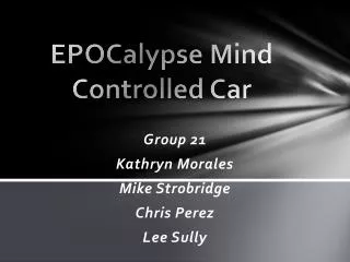
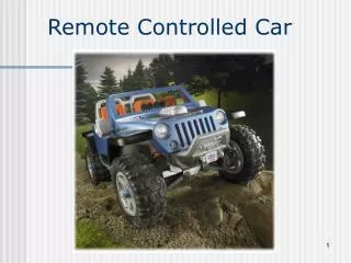
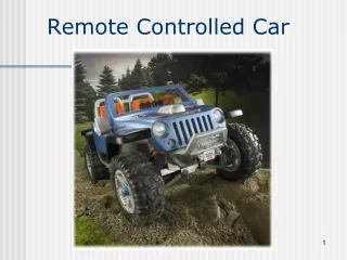
Introduction Gesture Control Car (GCC)is a microcontroller project that control the car motion by hand glove.
Introduction(Contd…) Most of controllers of existing remote cars require users to interface with joysticks and push buttons. Comparing to these conventional controllers, we built a wireless gesture controller which enables cars to mock hand motion in all dimensions.
GOAL • The goal of this project is to capture simple hand gestures from the Glove and use that input to wirelessly control car. Controlled variables include speed, steering, forward/reverse and stop.
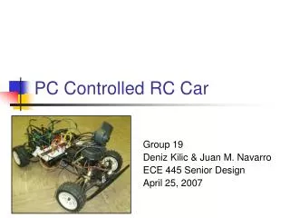
SYSTEM COMPONENTS 1. Glove 2. Microcontroller 3. X-Bee 4. car The Gesture Controlled car consists of four main components:
Glove component 1- Microcontroller 2- X-Bee 3- Flex sensor 4- Accelerometer 5- voltage regulator
Microcontroller • Themicrocontroller:is a small computer on a single integrated circuit containing a processor core, memory, and programmable input/output peripherals..
Hardware • Flex sensors : are sensors that change in resistance depending on the amount of bend on the sensor.
Hardware • Accelerometers: The accelerometer can detect the three-dimensional orientation of the hand . In our project we use ADXL335 is a triple axis accelerometer with extremely low noise and power consumption .
Hardware • Microcontroller : The processor that is used in our project is microcontroller Pic18F4620
XBee Series 1 Module • These modules allow a very reliable and simple communication between microcontrollers, computers, systems, really anything with a serial port! Point to point and multi-point networks are supported.
Car Component 1- Microcontroller 2- X-Bee 3- DC motor 4- uln2003a and l293d 5- resistors
How GCC Work? Transmitter side(Glove): When substrate flex sensor is bent the sensor produces a resistance output relative to the bend radius. The accelerometer measures the tilt of the user’s hand in the 3D XYZ plane.
How GCC Work? The microcontroller, MCU takes measurements from accelerometer to calculate the current tilt position of the hand and collects the values of two flex sensors to detect the bending of each finger. These sensors are directly connected to the microcontroller which is programmed so that it can process these sensors values and pass it to second part of the system.
Reading accelerometer value Reading flex1 Reading flex2 Do two ranges to move motor left or right . Also range for reference Divide the values into five ranges to control speed Glove flow chart Reading will be transmitted in the encoded form through X-Bee
How GCC Work? Receiver side(Car): The wireless car reads the signals sent by the gesture controller from the wireless modules and send it to MCU. MCU runs motors depending on data received to determine the movement, speed and directions.
Car flow chart Received the encoded data Run motors depending on data received to determine the movement , speed and direction Appropriate PWM will be fed to the L293d motor driver
Acceler- ometer Flex 2 Flex 1 Glove MCU Pic 18f4620 Whole system Data transmitting (X-Bee) Car MCU pic18f4620 Motor 1 Motor 2 PWM out put is fed to L293d motor driver
Problems and CONSTRAINTS: 1- accelerometer problem : the accelerometer destroyed and gave unstable values . We searched for the reason and we found that we fed it by more than 3.3 volt “completely damaged ”.
Solution Using voltage regulator fed 3.3 volt.
Problems and CONSTRAINTS: Sensitivity for Flex sensor : Its conductive material affected with usage and with the time there will notable variations of the output voltage range .
Future work - we will work to improve our idea "gesture controlling" to control any devices by any part of body not just by hand. - Also we will use our project to become helpful for people with special needs. - Games field.
Conclusion - All difficulties can be overcome by using Accelerometer and Gyroscopesensor. - Expensive !!!!!