Download
1 / 51
670 likes | 2.29k Views
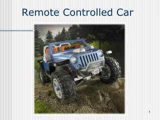
Remote Controlled Car. Team #: 4. Jordan Acevedo Phosay Bouapha Corey Preuss Ben Reider Lee Strauss. BSEE BSEE BSEE BSEE BSEE. Team #4: Expertise & Experience. Jordan Acevedo Phosay Bouapha Corey Preuss Ben Reider Lee Strauss.

E N D
Team #: 4 Jordan Acevedo Phosay Bouapha Corey Preuss Ben Reider Lee Strauss • BSEE • BSEE • BSEE • BSEE • BSEE
Team #4: Expertise & Experience Jordan Acevedo Phosay Bouapha Corey Preuss Ben Reider Lee Strauss • Expertise: Digital: PLD/FPGA VHDL, Soldering, Troubleshooting • Experience: 2 Year Internship at Rockwell Automation • Expertise: Analog: Amplifier, Filter Design • Experience: None • Expertise: Hardware, Software Validation, Mathematics Minor • Experience: 3 Internship Terms at GE Healthcare • Expertise: Power Supplies & Systems, Soldering, Business Minor • Experience: 2 Co-Ops at Kohler Corp. • Expertise: Power Supplies & Amplifiers • Experience: None
Team #4: Total Resources 10 Manhours/week $200 budget
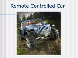
Proposed Product Summary Selected Product Remote Controlled Car Entertainment Details Miniature toy replica of a car, controlled remotely. Primary use of product is for entertainment and educational purposes. With proximity sensors, user is less likely to break product by running it into a wall. Yes there are similar products, but not identical due to fact of added damage protection and intended future use. Major industry family the product belongs to is consumer toys.
Project Selection Overall Selection Process The remote controlled car project provided more challenges and involved more complex aspects than the other projects. Major risks involve making sure all of our components work together well. Because our product contains moving parts, it is important that they work according to our specifications because safety concerns. Our other projects were rejected because they did not have enough blocks in the diagrams to satisfy our electronic requirements. This project was unanimously supported by all five members of our group.
System Level Performance Requirements Remote controlled (frequency band) Forward and Reverse, left and right steering, power Proximity sensors Detection of distance from nearby objects and emergency power shut off if car gets too close Headlights Headlights attached to front of car for illumination purposes. Can be turned on or off by the user from the remote control. Lights will also have dimming capability. Blinkers Array of 10 LEDs will click on or off based on user input to represent turn direction.
System Level Standard Requirements • 100 Total Parts • 30 Unique Parts • $150 (Parts+Mfg=Product Cost) • $50 (Parts+Mfg=Product Cost) • 4 yrs • 6 months • Repair • Max Parts Count • Max Unique Parts Count • Parts/Mat $ Allocation • Asm/Test $ Allocation • Product Life, Reliability • Full Warranty Period • Service Strategy
System Level Standard Requirements • Min Oper Temp Range • Min Oper Humidity Range • Min Oper Alt or Press Range • Min Storage Temp Range • Min Storage Humidity Range • Min Storage Alt or Press Range • Max Storage Duration • 0-60 Co • 20-95% non-condensing • 0-3500 Meters • 10-65Co • 0-90% non-condensing • 0-3500 Meters • 1 year
System Level Standard Requirements • Estimated Annual Income • Min List Price • Max Product Material Cost • Max Product Mfg Cost • Estimated Annual Contribution • Operating Voltage Range • $100000 • 300 • $80 • $30 • $50000 • 12V to 48V
Team Block Diagram DC-DC Converters Battery Motor PWM Microprocessor Proximity Sensor Dimming HeadLights Blinkers RF Signal
Ethics Considerations Since this is an entertainment product, the group did not see much room for conflicts of interest, bribery, and kickbacks. Safety can be an issue though; since children could play with the car, we’d have to make sure that the moveable parts are safe. While driving the car, someone could be hit, which could cause potential injury. To mitigate this, we need to make sure our proximity sensor switch works effectively. Legally, our remote controlled car could have problems if it is not differentiated enough from other cars in the market. Since remote controlled cars have been being manufactured for years, the idea is probably in the public domain. To stray from this, we will be using a remote controlled car of a larger size. Environmentally, the group doesn’t see any major considerations that must be made. We could try to find a more efficient power source, since batteries must be thrown away or recharged. Also, we could use more environmentally friendly solder and materials to minimize the effects of lead and other hazardous materials found in many components.
Applicable Patents Title: Radio control car • Document Type and Number: United States Patent 5334076 • There is no work around with this patent, royalties will be determined. Title: Recreational electric vehicle • Document Type and Number: United States Patent : 7243746 • This patent involves an indoor or outdoor vehicle for one or two people with a space for personal goods.. REV is driven using a joystick and is able to turn on the spot. Our design will not use a joystick that can control the vehicle in a 360 degree manner, but only in forward and reverse. Also our vehicle will not be primarily used for people to ride Title: Children's ride-on vehicle • Document Type and Number: United States Patent: D393888 • This is the actual patent for a power wheels vehicle that we will be using, therefore we must pay royalties.
Block 1: Power SuppliesOwner: Lee Strauss Power the system that runs and controls the car. Looking for +5 volts for operation Input of 12 volts from battery Buck Regulator used to achieve 5 volt output
Buck Regulator LM5005 Current: 250mA – 2.5A Operating Frequency: 50kHz to 500kHz Integrated 75V, 2.5A N-Channel Buck Switch Ultra-wide input voltage range from 7V to 75V Internal high voltage bias regulator Current mode control with emulated inductor current ramp Wide bandwidth error amplifier
Bill of Materials High Voltage Buck Regulator – LM5005 Capacitor 0.022uF – Part#: 08051C223JAT2A Capacitor 1uF – Part#: 08053D105KAT2A Capacitor 0.027uF – Part#: 08053D105KAT2A Capacitor 6.8 uF, 1.8ohms – Part#: EEV-FC1V6R8R Capacitor 10uF, 2ohms – Part#: EEV-FC1H100P Capacitor 0.003uF – Part#: GRM2165C1H302JA01D Capacitor 0.0082uF – Part#: 08055C822KAT2A Diode 0.5v – Part#: B130B-13 Inductor 330uH, 0.574ohms – Part#: DR127-331-R Resistor 1.43K ohms – Part#: ERJ-6ENF1431V Resistor 1K ohms – Part#: ERJ-8ENF1001V Resistor 2.26K ohms – Part#: ERJ-6ENF2261V Resistor 21K ohms – Part#: ERJ-6ENF2102V
Block 2: PWM Controller/Micro-ProcessorOwner: Jordan Acevedo
Block 2: PWM Controller/Micro-ProcessorDescription and Purpose The PWM Controller will receive a digital pulse transmitted from remote control and the width of the pulse will determine the desired speed of the car and the width of another pulse will determine the driving direction of the car (forward/reverse). Purpose: Control the speed and direction of the car.
Block 2: PWM Controller/Micro-ProcessorBlock Diagram In From Proximity Sensors Output to Motor Controller Pulse Width Modulation (PWM) Chip Input RF Signals Micro Processor In From Power Supply (+5V) In From Power Supply (+5V)
Block 2: PWM Controller/Micro-ProcessorBlock Signal Definitions
As the user presses forward on the remote control, the remote transmits pulses to the receiver. The width of two of these pulses will determine the speed and driving direction of the car. As the control stick on the remote is pressed further, the width of the pulses increases and the car will move faster in the desired direction. If the IR Proximity Sensors are tripped “ON”, the car will no longer be able to drive forward, when the sensors are “OFF” and then full operation will be restored. Block 2: PWM Controller/Micro-ProcessorTheory of Operation
Block 3: BlinkersOwner: Ben Reider Description - To receive and interpret a RF signal from controller and output a pulse that blinks either the right or left side blinkers on the car. Purpose – An accessory used to indicate which direction the car turn.
Block 3: Block Level Requirements • Must work off of a 5 Vdc power supplied • Must be able to handle a max current input of 150mA if needed to meet power supplies min current output. • Needs to operate within system temp. requirements of 0-60°C • Must read and interpret RF signal • Needs to relay power from battery in order to ensure brightness of lights • Needs to blink lights once every other second • Robustly build to protect against driving collisions • Low power dissipation • Low cost
Block #3Blinkers Block Diagram #2 12V Battery #1 5 VDC Power Supply #3 Microprocessor PIC12F509 8 Pin, DIP #6 MOSFET #4 MOSFET #7 Front Light Array 12V #7 Rear Light Array 12V #5 Front Light Array 12V #5 Rear Light Array 12V RF Signal
Block #3 Microprocessor Program Flow Diagram Start Check for pulse Signal Read in 5th pulse Measure width of 5th pulse Compare width to nominal value Check zero flag Z=0 LeftBlink=1 Z=1 RightBlink=1 Output Output 1 Sec Delay 1 Sec Delay Output LeftBlink=0 RightBlink=0 Output Interrupt 1 Sec Delay 1 Sec Delay Interrupt
Block #3 Component Selection LEDs Selected because in a series connection they could meet the change in source voltage(12-48V) Low cost and Long Lifetime Robustly built Low Power (144mW each) Transistors 60V Source to drain Voltage which meets the max source voltage of 48V Low power dissipation at 350mW Max Microprocessor Least expensive yet meet programming requirements 6 output/input Can handle the max current input of 150mA Lower Power (800mW Max)
Block 4: Proximity SensorOwner: Corey Preuss Part #: GP2Y3A003K0F (from Digikey) Wide Angle Distance Measuring sensor unit (40 – 300cm)
Block 4: Proximity SensorPreliminary Bill of Materials Part Mfg Part # Description Qty. Package Dimensions 1 GP2Y3A003K0F Wide Angle Distance 1 53x20x18mm Measuring Sensor Unit 2 Capacitor 10uF 1 ---
Block 4: Proximity SensorCalculations and SpecificationsAbsolute Maximum Values/Limits Measuring Distance Range: 40-300cm # of Outputs/Type: 5 Analog Outputs Detection Angle: 25 Degrees Supply Voltage Range (Vcc): -0.3 to +7V Output Terminal Voltage(Vot): -0.3 to Vcc(+0.3V) Input Voltage(Vin H/L and LED H/L): -0.3 to +Vcc(0.3V) Operating Temperature(Topr): -10 to +60 Degrees Celcius Storage Temperature: -40 to +70 Degrees Celsius
Block 4: Proximity SensorCalculations and SpecificationsElectro-optical Characteristics Average Supply Current(Icc Ave./Max.): 30/50mA Ideal Supply Voltage(Vcc): 4.5 to 5.5V Output Voltage(Vo): Min: 2.0 Ave: 2.3 Max: 2.6V Output Voltage Differential(ΔVo): Min: 0.9 Ave: 1.2 Max: 1.5V (between 40cm and 100cm) Input Voltage: VinH: 4.5V(min.) VinL: 0.3V(max.) LED H: 4.5V(min.) LED L: 0.5V(max.)
Block 4: Proximity SensorTheory of Operation Proximity switch receives input voltage and current from power supply via the microprocessor Sensor measures distance to nearby object If object is close enough to trigger the sensor “ON”, an interrupt will be sent through the microprocessor to the motor disabling the car’s forward position movement Vehicle will be allowed to move in reverse direction until proximity sensor is switched “OFF”, and the car will then be allowed to move forward
Block 4: Proximity SensorDescription and Purpose Sensor used for measuring distance from the car to nearby objects and sending a signal to the motor via the microprocessor to shut off if it gets too close to the object. Car will then only be allowed to move in reverse until it is a safe distance away from the object and will then be allowed to move forward. Operation is used for safety concerns
Block 5: Dimming Headlights • Description – Circuit to dim the headlights when the car is in a bright environment, while operating in a bright environment, the head lights will be at max brightness. • Purpose – An accessory used to allow the car to automatically control the headlights by it self.
Block 5: Dimming HeadlightsBlock Diagram P722-5R +5V Power Supply -12V Power Supply Photo-resister 2 x Inverting op-amps Left Head light Right Head Light +12V Battery
Block #5 Detailed Design Calculations and Component Selection • Lights • Selected because of price and efficiency. • Long Lifetime • Low Power (144mW each) • Photo-Resistor • Type(P722-5R) • Resistance range of 15KOhms at 1 lux to 1.1KOhms at 100 lux • Has desired performance range • Power dissipated (70mW) • Op-amp • Inexpensive and meets performance requirements
Block 5: Proximity SensorPreliminary Bill of Materials • Description • Photo-resistor • Op-amp • Resistor • Lights(LED) • Qty.1 • 2 • 4 • 60 • Price(each) • $0.40 • $0.22 • $0.054 • $0.23 Total cost = $14.86 • Part # 276-1657(Radio Shack) LM741CN 1.0KQBK-ND SSL-LX3044YD-12V
Bright environment (100lux) max photocell resistance(Rp) Block 5
Output Voltage in bright environment (100lux) max photocell resistance Block 5
Dark environment (1lux) min photocell resistance(Rp) Block 5
Output Voltage in dark environment (1lux) min photocell resistance Block 5