GESTURE CONTROLLED ROBOT
1.01k likes | 3.32k Views
GESTURE CONTROLLED ROBOT. An insignia on technology. By. MOHD HARIS SIDDIQUI. 2 nd Year. Md. AFTAB USMANI. 2 nd Year. Md. RASHID AZAM. 2 nd Year. CONTENT. Introduction Components Used Components Specifications Complete schematics Code Algorithm Applications Conclusion

GESTURE CONTROLLED ROBOT
E N D
Presentation Transcript
GESTURE CONTROLLED ROBOT An insignia on technology By MOHD HARIS SIDDIQUI 2nd Year Md. AFTAB USMANI 2nd Year Md. RASHID AZAM 2nd Year
CONTENT • Introduction • Components Used • Components Specifications • Complete schematics • Code • Algorithm • Applications • Conclusion • Acknowledgement • References
INTRODUCTION Gesture recognition enables humans to communicate with the machine and interact naturally without any mechanical devices. These gestures can originate from any bodily motion or state but commonly originate from the face or hand. In this project we have tried to control a robot by hand gestures using an accelerometer sensor in conjunction with a MCU and RF link.
Accelerometer ADLX335 100 rpm DC motors COMPONENTS USED MCU Atmega16 RF Link 434 MHz HT12E Decoder IC Motor Driver (L293D) Voltage regulator (7805) HT12D Encoder IC
Components Specifications • Accelerometer Sensor The ADXL335 is a small, thin, complete 3-axis accelerometer. It measures acceleration with a minimum full-scale range of ±3 g. It is can be used in the static as well as dynamic applications.
Components Specifications • RF Link 434 MHz This RF link comprises of an RF Transmitter and an RF Receiver. The (Tx/Rx) pair operates at a frequency of 434 MHz. An RF transmitter receives serial data and transmits it wirelessly through RF through its antenna connected at pin4. The transmitted data is received by an RF receiver operating at the same frequency as that of the transmitter.
Components Specifications • HT12E Encoder IC HT12E is an encoder integrated circuit of 212 series of encoders. It encodes the 12 bit parallel data into serial for transmission through an RF transmitter. These 12 bits are divided into 8 address bit s and 4 data bits.
Components Specifications • HT12D Decoder IC It is a decoder integrated circuit that belongs to 212 series of decoders.It is capable of decoding 12 bits, of which 8 are address bits and 4 are data bits. The data on 4 bit latch type output pins remain unchanged until new is received.
Components Specifications • 100 rpm DC motors It is a low cost DC motor suitable for most robotic and general applications. It has a output shaft with a hole for easy mounting of wheels or pulleys. Input Voltage: 6-12 V Stall Current: 500 - 600 mA Shaft length: 2.4 cm
Components Specifications • Motor Driver The L293 and L293D are quadruple high-current half-H drivers. The L293 is designed to provide bidirectional drive currents of up to 1 A at voltages from 4.5 V to 36 V. The L293D is designed to provide bidirectional drive currents of up to 600-mA at voltages from 4.5 V to 36 V.
Components Specifications • MCU Atmega16 It is Low-power AVR8-bit Microcontroller with 16KB In-System Self-Programmable Flash.It has 32 Programmable I/O Lines with Real Time Counter with Separate Oscillator & Four PWM Channels
Components Specifications • Voltage regulator (7805) 7805 is a voltage regulator integrated circuit. The voltage regulator IC maintains the output voltage at a constant value. It provides +5V regulated power supply.
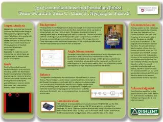
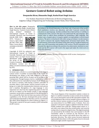
Complete Schematics Transmitter Side Image from simulation file of Proteus
Complete Schematics Receiver Side Image from simulation file of Proteus
CODE Transmitter side: while (1) { x=read_adc(0); y= read_adc(1); itoa(x,a); itoa(y,b); lcd_gotoxy(0,0); lcd_putsf("X axis="); lcd_gotoxy(0,1); lcd_putsf("Y axis="); lcd_gotoxy(10,0); lcd_puts(a); lcd_gotoxy(10,1); lcd_puts(b); PORTB=0x00; if(x>370) PORTB=0b00000001; else if(x<280) PORTB=0b00000010; else if(y>370) PORTB=0b00000100; else if(y<290) PORTB=0b00001000; }
CODE Receiver Side while(1) { if(PIND&(1<<4)) motor_forward(); else if(PIND&(1<<5)) motor_backward(); else if(PIND&(1<<6)) motor_left(); else if(PIND&(1<<7)) motor_right(); else motor_stop(); } }
ALGORITHM • Transmitter Side
ALGORITHM • Receiver Side
APPLICATIONS • Hospitals Wheel Chair Control Hospital Bed Control
APPLICATIONS • Industrial Robots Robotic Arm Control Self Controlled Humanoids
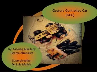
APPLICATIONS • Automobiles Gesture Controlled Cars!!
Limitations & Further Developments Hardware Complications Speed Control Specific gestures
Conclusion Gesture control which is a emerging technology finds many applications in various fields. The work we have done is a little part of it. Controlling the motion of wheeled robot through this system is not the only thing, with further research we can take it too far.
REFERENCES 1. http://www.wikipedia.org 2. http://www.freescale.com 3. http://www.ablabs.co.in 4. http://www.onlinetps.com 5. http://www.atmel.com
ACKNOWLEDGEMENT • AMU ROBOCLUB.