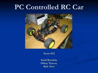
Remote Controlled Car
Team #4 presents an advanced remote-controlled car designed for entertainment, featuring unique enhancements such as proximity sensors to prevent collisions, adjustable headlights based on environmental lighting, and directional blinkers activated by remote control. With a focus on safety and user experience, this toy car promises enjoyment without compromising on reliability. Our team utilizes expertise in digital and analog design, with valuable internship experiences from major companies. This product aims for a worldwide market, appealing to both recreational enthusiasts and educational sectors.


Remote Controlled Car
E N D
Presentation Transcript
Team #: 4 Jordan Acevedo Phosay Bouapha Corey Preuss Ben Reider Lee Strauss • BSEE • BSEE • BSEE • BSEE • BSEE
Team #4: Expertise & Experience Jordan Acevedo Phosay Bouapha Corey Preuss Ben Reider Lee Strauss • Expertise: Digital: PLD/FPGA VHDL, Soldering, Troubleshooting • Experience: 2 Year Internship at Rockwell Automation • Expertise: Analog: Amplifier, Filter Design • Experience: None • Expertise: Hardware, Software Validation, Mathematics Minor • Experience: 3 Internship Terms at GE Healthcare • Expertise: Power Supplies & Systems, Soldering, Business Minor • Experience: 2 Co-Ops Terms at Kohler Corp. • Expertise: Power Supplies & Amplifiers • Experience: None
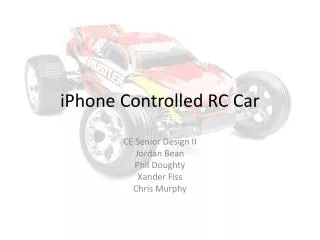
Proposed Product Summary Selected Product Remote Controlled Power Wheels Car Purpose: Entertainment Details Miniature toy replica of a car, controlled remotely. Unique additions: Proximity sensors, user is less likely to break product by running it into a wall. Remote control triggered directional blinkers. Headlights adjustable to environmental intensity. There are similar products, but not identical due to unique additions. The major industry family the product belongs to is consumer toys.
Project Selection Overall Selection Process The remote controlled car project provided more options for individual blocks. Major risks involve making sure all of our components work together well. Because our product contains moving parts, it is important that they work according to our specifications because safety concerns. Our other projects were rejected because they did not have enough blocks in the diagrams to satisfy our electronic requirements. This project was unanimously supported by all five members of our group.
System Level Performance Requirements Remote controlled (frequency band) Forward, Reverse, and Speed Sensitive Proximity sensors Detection of distance from nearby objects and emergency power shut off if car gets too close. Headlights Headlights attached to front of car for illumination purposes. Can be turned on or off by the user from the remote control. Lights will also have dimming capabilities dependant on surrounding environment. Blinkers Array of LEDs that will blink based on RF input from the remote control to represent turn direction.
System Level Standard Requirements • 142 Total Parts • 25 Unique Parts • $105 (Parts+Mfg=Product Cost) • $50 • 4 yrs • 6 months • Repair • Max Parts Count • Max Unique Parts Count • Parts/Mat $ Allocation • Asm/Test $ Allocation • Product Life, Reliability • Full Warranty Period • Service Strategy
Market • Common Competitor: No true competitor in similar scale, though many competitors in the remote controlled car field. • List Price: $475 • Our Add On Portion: 30% ($142.50) • Market Geography: Worldwide • Market Demography: Adults • Market Industry: Recreation, Education • Material Cost: $105 • Manufacturing Cost: $25 • Annual Volume: 10,000
Return On InvestmentAdjusted to Add On Portion • Annual Revenue: $1,425,000 • Cost Margin: $12.50 • Cost Margin %: 8.77% • Annual Cost Margin: $125,000 • Development Cost: $20,000 • ROI: $45,000/$125,000 = 36.0%
System Level Standard Requirements • Min Oper Temp Range • Min Oper Humidity Range • Min Oper Alt or Press Range • Min Storage Temp Range • Min Storage Humidity Range • Min Storage Alt or Press Range • Max Storage Duration • 0-60 Co • 20-95% non-condensing • 0-3500 Meters • 10-65Co • 0-90% non-condensing • 0-3500 Meters • 1 year
Performance Requirements • Remotely Controlled at 75.97 KHz • Able to operate at various battery voltages (12-48V) • Capable of speed regulated forward and reverse • Remote Controlled directional lights • Dimming Headlights • Proximity sensing collision protection
Team Block Diagram DC-DC Converters Battery Motor PWM Microprocessor Proximity Sensor Dimming HeadLights Blinkers Lee Strauss Jordan Acevedo Ben Reider Corey Preuss Phosay Bouapha RF Signal
Applicable Patents Title: Radio control car • Document Type and Number: United States Patent 5334076 • There is no work around with this patent, royalties will be determined. Title: Recreational electric vehicle • Document Type and Number: United States Patent : 7243746 • This patent involves an indoor or outdoor vehicle for one or two people with a space for personal goods.. REV is driven using a joystick and is able to turn on the spot. Our design will not use a joystick that can control the vehicle in a 360 degree manner, but only in forward and reverse. Also our vehicle will not be primarily used for people to ride Title: Children's ride-on vehicle • Document Type and Number: United States Patent: D393888 • This is the actual patent for a power wheels vehicle that we will be using, therefore we must pay royalties.
Block 1: Power SuppliesOwner: Lee Strauss Power the system that runs and controls the car. Looking for +5 volts for operation Input of 12 volts from battery Buck Regulator used to achieve 5 volt output
Buck Regulator LM5005 Current: 250mA – 2.5A Operating Frequency: 50kHz to 500kHz Integrated 75V, 2.5A N-Channel Buck Switch Ultra-wide input voltage range from 7V to 75V Internal high voltage bias regulator Current mode control with emulated inductor current ramp Wide bandwidth error amplifier
Bill of Materials High Voltage Buck Regulator – LM5005 Capacitor 0.022uF – Part#: 08051C223JAT2A Capacitor 1uF – Part#: 08053D105KAT2A Capacitor 0.027uF – Part#: 08053D105KAT2A Capacitor 6.8 uF, 1.8ohms – Part#: EEV-FC1V6R8R Capacitor 10uF, 2ohms – Part#: EEV-FC1H100P Capacitor 0.003uF – Part#: GRM2165C1H302JA01D Capacitor 0.0082uF – Part#: 08055C822KAT2A Diode 0.5v – Part#: B130B-13 Inductor 330uH, 0.574ohms – Part#: DR127-331-R Resistor 1.43K ohms – Part#: ERJ-6ENF1431V Resistor 1K ohms – Part#: ERJ-8ENF1001V Resistor 2.26K ohms – Part#: ERJ-6ENF2261V Resistor 21K ohms – Part#: ERJ-6ENF2102V
Block 2: PWM Controller/Micro-ProcessorOwner: Jordan Acevedo
Block 2: PWM Controller/Micro-ProcessorDescription and Purpose The PWM Controller will receive a digital pulse transmitted from remote control and the width of the pulse will determine the desired speed of the car and the width of another pulse will determine the driving direction of the car (forward/reverse). Purpose: Control the speed and direction of the car.
Block 2: PWM Controller Block Diagram Power Supply (+5V) In From Front Proximity Sensors NOT Gate (Direction) To Motor AND Gate In From Rear Proximity Sensors Input RF Signals Micro Processor (Speed) To Motor Power Supply (+5V) 23
Block 2: PWM Controller/Micro-ProcessorBlock Signal Definitions
As the user presses forward on the remote control, the remote transmits pulses to the receiver. The width of the second pulse will determine the speed and driving direction of the car. As the control stick on the remote is pressed further, the width of the pulses increases and the car will move faster in the desired direction. If the Front or Rear IR Proximity Sensor are tripped “ON”, the car will no longer be able to drive in that direction, when that sensor is “OFF” again, full operation will be restored. Block 2: PWM ControllerTheory of Operation 25
Block 3: BlinkersOwner: Ben Reider Description To receive and interpret a RF signal from controller and output a pulse that blinks either the right or left side blinkers on the car. Purpose An accessory used to indicate which direction the car turn.
Performance Requirements • Power Inputs • 5V Supply • 2 – 5.5 VDC • 20mA • 12V Supply • 10 – 14.8 VDC • 60mA • Max Total Power Displaced • 2.31 Watts • Operation Modes • On/Off • User Interface • Remote Controlled
Standard Requirements • Electrical Interfaces • 5VDC @ 250mA Power Supply • 12V Battery • 75.95 KHz Input Frequency • 1 Hz Output Frequency • Environmental • Operating Temp Range • Operating Humidity Range • Operating or Press Range • Storage Temp Range • Storage Humidity Range • Storage Altitude or Press Range • -40-85 C° • 20-95% non-condensing • 0-3500 Meters • -65-150C° • 0-90% non-condensing • 0-3500 Meters
Standard Requirements • Manufacturing • Block Cost • Part Count • Unique Part Count • Block Size • Block Mass • Block Volume • $5.01 • 53 • 4 • 15X20mm Light Arrays • 2.8”X3.8” PCB Board • ?? • ??
Block #3Blinkers Block Diagram 12V Battery 5 VDC Power Supply Microprocessor PIC12F509 8 Pin, DIP PNP Transistor PNP Transistor Front Light Array Rear Light Array Front Light Array Rear Light Array RF Signal
Theory Of Operation • Micro-Controller receives RF input • Ignores pulses prior to 5th pulse • Measures pulse width of 5th pulse • Interprets which directional blinkers should be activated • Outputs a 5V pulse @ 1 Hz • Transistors receives 1 Hz input • Switches 12V source @ 1 Hz to LEDs
Block #3 Microprocessor Program Flow Diagram Start Check for pulse Signal Read in 5th pulse Measure width of 5th pulse Compare width to nominal value Check zero flag Z=0 LeftBlink=1 Z=1 RightBlink=1 Output Output 1/2 Sec Delay 1/2 Sec Delay Output LeftBlink=0 RightBlink=0 Output 1/2 Sec Delay 1/2 Sec Delay
Block #3 Component Selection LEDs Low cost and Long Lifetime Robustly built Low Power (40mW each) Transistors 40V Source to drain Voltage which meets and well exceeds the source voltage of 12V Low cost Low power dissipation at 350mW Max Microprocessor Least expensive yet meet programming requirements 6 output/input Can handle the max current input of 150mA Lower Power (800mW Max) Resistor 12V Input with 3 parallel rows of 4 LEDs in series and a transistor voltage drop Voltage Applied: 12V-(2V*4)-0.4V = 3.6V Current Applied: 20mA + 20mA +20mA 3.6/0.06 = 60 Ohms @ 200mW
Block 4: Proximity SensorOwner: Corey Preuss Part #: GP2Y3A003K0F (from Digikey) Wide Angle Distance Measuring sensor unit (40 – 300cm) 39
Block 4: Block Level Requirements • Must work off of a 5 Vdc power supplied • Must be able to handle a max current input of 50mA if needed • Needs to operate within system temp. requirements of -10 to 60°C • Must be able to detect distance between 2ft and 6ft • Must supply a voltage output of at least 2V to Microprocessor for logic operation 40
Block 4: Proximity SensorCalculations and SpecificationsAbsolute Maximum Values/Limits Measuring Distance Range: 40-300cm # of Outputs/Type: 5 Analog Outputs Detection Angle: 25 Degrees Supply Voltage Range (Vcc): -0.3 to +7V Output Terminal Voltage(Vot): -0.3 to Vcc(+0.3V) Input Voltage(Vin H/L and LED H/L): -0.3 to +Vcc(0.3V) Operating Temperature(Topr): -10 to +60 Degrees Celcius Storage Temperature: -40 to +70 Degrees Celsius 41
Block 4: Proximity SensorCalculations and SpecificationsElectro-optical Characteristics Average Supply Current(Icc Ave./Max.): 30/50mA Ideal Supply Voltage(Vcc): 4.5 to 5.5V Output Voltage(Vo): Min: 2.0 Ave: 2.3 Max: 2.6V Output Voltage Differential(ΔVo): Min: 0.9 Ave: 1.2 Max: 1.5V (between 40cm and 100cm) Input Voltage: VinH: 4.5V(min.) VinL: 0.3V(max.) LED H: 4.5V(min.) LED L: 0.5V(max.) 42
Block 4: Proximity SensorTheory of Operation Proximity switch receives input voltage and current from power supply via the microprocessor Sensor measures distance to nearby object (40cm to 300cm) If object is close enough to trigger the sensor “ON”, the output will be sent through an inverting gate to the microprocessor disabling the car’s forward or backward position movement Vehicle will be allowed to move in reverse direction only if front sensor is triggered and forward direction only if rear sensor is triggered until the given sensor is switched “OFF”, and the car will then be allowed to move in that direction 43
Block 4: Proximity SensorPurpose and Description Operation is used for safety concerns Sensors detect objects nearby to stop vehicle and prevent potential injury Helps prevent damage to the car itself 44
Block 4: Proximity SensorBlock Diagram Breakdown/Schematic 45
Block 4: Proximity SensorPreliminary Bill of Materials Part Mfg Part # Description Qty. Cost 1 GP2Y3A003K0F Wide Angle Distance 2 $52.50(each) Measuring Sensor Unit 2 PCC2169CT-ND Capacitor 10uF 2 $1.44(each) 46
Block 5: Dimming Headlights 50 • Description – Circuit to dim the headlights when the car is in a bright environment, while operating in a bright environment, the head lights will be at max brightness. • Purpose – An accessory used to allow the car to automatically control the headlights by it self.