Download
1 / 27
270 likes | 406 Views
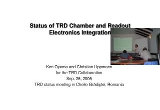
Status of TRD Chamber and Readout Electronics Integration. Ken Oyama and Christian Lippmann for the TRD Collaboration Sep. 26, 2005 TRD status meeting in Cheile Gr ă di ş tei, Romania. Contents. Investigation for reducing noise.

E N D
Status of TRD Chamber and Readout Electronics Integration Ken Oyama and Christian Lippmann for the TRD Collaboration Sep. 26, 2005 TRD status meeting in Cheile Grădiştei, Romania
Contents • Investigation for reducing noise. • Remove external noise by good groundings and good H.V. connections. • Testing of new type regulators with charge pump. • Using pre-final power bus bar and its load test. • Using prototype water cooling pipes and check noise level with it.
Situation Today test beam stack • What is different since before? • Power bus bar is there. • Cooling pipes are there. • Better HV connections. • Recently, TRD test beam stack is mainly operated by M.Gutfleisch with the cosmic trigger, stably. • Study for integration and grounding are mainly done for the stand alone chamber (S.A.C.) outside the stack. single MCM instead of T3 ROBs L1C0 stand alone chamber (S.A.C.) fully covered by the 6 T4 ROBs DCS (for CLK, Trig, SCSN) independently powered
Load Test of the Prototype Power Bus Bar A prototype power bus bar with 4 pairs of copper plates ( 0.7 mm x 50 mm each) was tested. 40 A current for each pair is given without cooling (total 160 A). Result Voltage drop in 60 cm bar at 40 A load current = 16 ± 1 mV 27 mV/m 0.67 mΩ/m. Expected resistance is 0.5 mΩ/m for pure copper at room temperaturewhile our measurement is 34 % larger. Maximum voltage drop in supermodule will be ~200 mV. The bar had no significant heat (~ human skin) except for around the short cut point.
Noise Measurement (1) Before bus bar installation (2) After bus bar installation pos5 #23 1.22 pos4 #24 1.30 pos5 #23 1.18 pos4 #24 1.15 pos3 #27 1.40 pos2 #28 1.44 pos3 #27 1.20 pos2 #28 1.24 average 1.23 ( 10 % better ) average 1.37 pos1 #25 1.45 pos0 #26 1.40 pos1 #25 1.32 pos0 #26 1.27 (3) If we exchange pos 1 and 5 ROB’s pos5 #25 1.35 pos4 #24 1.13 Noise looks associated to rob type and regulator type. pos3 #27 1.17 pos2 #28 1.26 pos1 #23 1.19 pos0 #26 1.32 memo: excluded dead or disconnected MCM’s for all measurements.
Noise Measurement T4#0025 with new regulator T4#0023 with old regulator new regulators sitting here
Noise from Charge Pump AC component on 5 V pumped line on patchworks without capacitors With two 470 uF capacitors on 5 V pumped line 5V charge pump output (AC cpl.) 40 mV PASA output
Noise Level with Capacitances on Pumped Lines Two 470 uF for pos5: pos5 #25 1.27 pos4 #24 1.12 pos3 #27 1.18 pos2 #28 1.21 pos1 #23 1.17 pos0 #26 1.26 • Capacitors help but not yet perfect. • Turning off of pos3 and pos2 did not help. • Extra shielding and battery driving of charge pump did not help. • Increasing connections among ROB’s help a bit but not yet perfect. • Connecting HV GND of filter box to carbon surface did not help.
Improving H.V. Connections HV Improving # pos5 #25 1.06 pos4 #24 1.04 pos3 #27 OFF pos2 #28 OFF pos1 #23 1.10 pos0 #26 1.16 # direct connection of HV GND to pos4 ROB GND and better handling of cables. • It was found that noise is significantly reduced (> 60 e) if we connect H.V.GND of H.V. filter box to PASA GND on nearest ROB (number above). • C.Lippmann found that pos0 noise significantly increased at some point (> to 1.3 LSB). This gave us a hint that handling of H.V. connection from filter box to ROB is really important.
The Best Situation Till Now Last steps were: • All HV cables from filter box to anode segments were cut to appropriate length (25 cm for row0 and 1). And well gathered and taped so that loop area is minimized. • Red (final) HV cables from HV distribution box to filter box with length similar to that in the super-module, SHV connectors of filter box replaced by soldering. This gives little bit less noise but not significant. • With these connections, noise level does not increase significantly even if you switch back to using charge pump (less than 20 e contribution). • No additional shielding by aluminum foils around chamber is necessary. pos5 #25 1.05 pos4 #24 1.03 pos3 #xx OFF pos2 #28 OFF pos1 #23 1.03 pos0 #26 1.04 average: 1.038
Long Term Stability of Noise Level Although small excess is at 8 o’clock Sep.12, noise level is very stable in ±10 electrons.
Testing with Water Cooling Pipe Made by A. Marin Cooling water pipes & plates on only MCM0-7 on Position 0 ROB Grounding by copper strip to ROB PASA GND • Result Average RMS for MCMs under the pipes • without pipe : 1.08 LSB (1.08 for Pos1) • no grounding of pipe : 1.09 LSB (1.08 for Pos1) • grounding to L-profile : 1.10 LSB (1.09 for Pos1) • grounding to PASA GND : 1.08 LSB (1.08 for Pos1) • Conclusion • No significant effect due to pipes but grounding to PASA GND looks the best. Probably It is safer to have this option.
ADC-PASA noise measurements(2) http://www-alice.gsi.de/trd/meetings/status/050425/venelin_20050425.ppt David Muthers, Kaiserslautern
Pad Capacitance Dependence measurement on L1C0 S.A.C (1.04 in avg.) without pad connections (0.64 in avg.) • Pad C are from D.Emschermann’s measurements on L1C1 chamber, and scaled for L1C0 chamber using difference of PAD sizes (80 / 75 and 90 / 75 for row 0 and 1, respectively). • In addition, 3.5 pF due to connectors, balls, and traces on ROB and MCM is added. • Measurement from D.Muthers and I.Rusanov were multiplied by 1000/1200 because ADC range setup is different between their measurement and our S.A.C. Note: Fit result for ROB on Chamber thru ADC is: 0.020 * C + 0.577 LSB’s. Line width show 2 sigma deviation. Chi2 / NDF= 2.2 / 473.
Conclusions • Noise level is significantly improved from ~1.37 LSB (1560 e) to ~1.04 LSB (1250 e). • Finalizing grounding method and H.V. connections were almost done but still maybe we can improve (900 e nolse contribution might be still there). We can investigate whether the noise level stays like now in LSB if we vary gain setup of ADC, and check what is the dominant source is 900 e noise. • Testing of power bus bar was done. • Basic test of water pipe was done and there was no significant effect in noise level.
ADC-PASA noise measurements(3) David Muthers, Kaiserslautern
Current per bus bar: Digital 3.3V 8 A + ~5 A TRAP + OASE Digital 1.8V 35 A ADC Analog 1.8V 38 A ADC Analog 3.3V 29 A PASA Digital and Analog should not be mixed: Digital 48 A Analog 67 A * Analog should be closer to the cooling water pipe * PASA can not be touched to digital so … Digital 3.3V ~13 A Digital 1.8V 35 A Analog 1.8V 38 A Analog 3.3V 29 A cooling
ADC-PASA noise measurements(1) David Muthers, Kaiserslautern
Noise Measurements 2 • strong effect of badly routed pre-trigger line. • But most of them have no problem.