Download
1 / 22
220 likes | 350 Views
This report provides an overview of the TRD (Transition Radiation Detector) setup at CERN, operational after just two days. It details the system architecture, including the DCS (Detector Control System) configurations and controlling elements such as Low Voltage (LV), High Voltage (HV), and gas systems. It highlights cable management, electronic distributions, and the integration of various modules and panels for efficient operation. Furthermore, issues related to logging in PVSS and operational control through OPC are discussed, alongside the progression of developments within the system.

E N D
DCS Status of TRD G. Tsiledakis University of Heidelberg R. Bramm,T. Dietel, B. Doenigus, D. Emschermann, T. Krawutschke, C. Lippmann, J. Mercado, K. Oyama, B. Schockert, K. Schweda, J. Steckert, M. R. Stockmeier DCS Workshop-ALICE Week CERN, Monday 9 October 2006
TRD at CERN Fully operated after only 2 days of setup
module MCM 6 planes TR-detector 18 channels chamber B=0.4T vertex max. 16 padrows 5 module rings 8 MCM 144 channels 18 sectors in azimuth r z TRD structure • Radius from 2.5 m - 3.7 m • Length 7 m • 18 Super Modules • 540 Chambers (720 m2) • 4.104 ReadOutBoards • ~70.000 MultiChipModules • 1.200.000 Channels
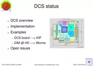
Detector Control System (DCS) DCS controls/monitors: • Low Voltage (LV) • High Voltage (HV) • Front-end electronics (FEE) • Gas/Cooling • Pre-trigger system • Power distribution box for dcs-boards Hardware view
Low Voltage • 5 power supplies : Wiener/PL512 • Control by OPC server or SNMP (Ethernet) • PVSS basic operation ready for 1stSM • LV is in use at CERN at SXL2
Operation panel for LV Failure Max Current Failure Max Sense Voltage Failure Max Term. Voltage Failure Min Sense Voltage diagnostics settings
Operation panel for LV read actual values V, A
HV - ISEG PVSS panel for layer 0 -Input for HV distribution system by University of Athens • OPC V4.02: switching on/off • individual channels is OK • Peak CAN USB adapter • works fine
HV Distribution System • 8 Anode + 8 Drift assembled cards • 10 auxiliary power supply cards with 3 transformers/card • 3 backplanes (one spare) • 2 crates • Markouizos, A. Mantzaridis, P. Mitseas, A. Petridis, • S. Potirakis, M. Tsilis, M. Vassiliou University of Athens
HVDS output stability U (mV) 1600 V with resolution of 30 mV (overnight measurements) t (s)
PVVS-Inject FED Server InterCom Layer FEE Client • Commands sent from PVSSFEE Server Using InterCom/Config/FEE Server for ROC tests • Problems with logging in PVSS • Further development is ongoing… FEE Server FEE Server FEE Server FEE Chain (3 Layers) PVSS (DIM - Client) #1 User: 1 PVSS/FSM #2 Intermediate: 1 InterCom + DB #3 540 DCS boards 8(6) ROBs each: ControlEngine / FeeServer Config. DB CommandCoder
Gas controls • Gas system will be controlled by PVSS panels that talk to the PLC. • Software was developed by IT/CO and now is debugged and tuned by the gas working group • Goofie (drift velocity, gain, gas composition) via a DIM server to a machine where the DCS can retrieve them via PVSS • Common effort with the TPC team C. Garabatos, U. Frankenfeld
Cooling The (prototype) C&V Framework component is used • Provides simple common panels for development and debugging in Device Editor and Navigator • The SCY file which contains data about the variables in the PLC has just been provided for TRD • After the C&V tool is working it will be integrated into a FSM control panel • Functionality and understanding of SCY file is in progress… • Soon connection with hardware A.Tauro, M. Dos Santos, G.De Cataldo
Open Issues • Low Voltage • Supervision behavior exists but is not controlled by PVSS bug in the framework reported to JCOP… • ramp speed changed from 100 V/s to 1 V/s via USB needs to be part of PVSS !
Open Issues • High Voltage • Using bit masking to switch ON/OFF the channels in OPC V4.10 is ok, but difficult to implement in PVSS • OPC V4.02 has the desired functionality (tests have started) • Frond-end electronics • Logging issues in PVSS
Summary 1st TRD supermodule is operated above ground • LV: is in use at CERN • HV: OPC V4.02 is OK • FEE: basic functionality available, further development… • Gas/Cooling: provided components are tested… • PDB: first dcs-chain set up, work in progress… • FSM development in progress…
fwWiener PVSS framework component 6 LV supplies 18 channels 24 panels for the 1st supermodule • We need just 1 simple panel for operating everything
HV • A special DCS Board Firmware is developed for the HVDS system Communication hierarchy