Download
1 / 25
250 likes | 371 Views
KTAG Mechanics, Optics and Cooling. Progress and Schedule. KTAG Schedule for Technical Run. Build stage-1 detector January 2012 to July 2012 Half detector (4 octants) [Incorporate improvements later] 32-channel readout [Final design is 64] Preliminary optics [defer cost and complexity]

E N D
KTAG Mechanics, Optics and Cooling Progress and Schedule NA62 CEDAR Meeting 3May2012
KTAG Schedule for Technical Run • Build stage-1 detector January 2012 to July 2012 • Half detector (4 octants) [Incorporate improvements later] • 32-channel readout [Final design is 64] • Preliminary optics [defer cost and complexity] • CEDAR Activities May – December 2012 • Dry run and DAQ integration 15 – 31 July • Complete and test KTAG in UK 31 July • Install KTAG & Integration August - September • Technical Run 12 October – 9 December • Data to understand beam backgrounds, finalise Mechanics & Optical design and understanding of DAQ & Electronics for 2014 NA62 CEDAR Meeting 3May2012
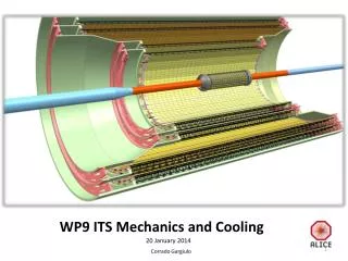
Octant Cooling block HV connectors ATEX nitrogen enclosure Quartz lens 90o spherical mirror Support cylinder bolted to CEDAR Lightguide Support Cylinder bolted to CEDAR flange Detector frame NA62 CEDAR Meeting 3May2012
Liverpool Design and Fabrication Design Fabrication • Support Tube Installed on CEDAR Nose • Light guide 1 Completed • Remaining 3 lightguides End of May • Detector Framework Assembled in Liverpool • Optical support cylinder Completion end of May • ATEX-2 chamber & supports Completion immanent • Lens & mirror mounts Outside company – end of May • Cooling assembly – May Completion mid June (in house) • Environmental Case & Frame • Materials arrive & cut at RohaSell 25th May -> 2nd June • Panels encased in aluminium Delivery 15th June • Installation Frame Completion mid June • Lightguide & electronics box Components (outside company) – May • Integration of cooling & electronics June NA62 CEDAR Meeting 3May2012
Development Work Gluing conical inserts Measuring reflectivity Cooling and Chiller NA62 CEDAR Meeting 3May2012
Gluing method • Standard aluminium surface preparation • Removing loose particles • Degreasing • Polishing cone or fitting aluminised-mylar insert • Mylar mounting - vacuum pen development NA62 CEDAR Meeting 3May2012
Gluing of aluminised mylar (update) Procedure • Mylar covered (electrostatically) with protective layer of food-wrap, “sandwiched” in layers of 10 • Conical inserts cut with the use of a template • Degreased Al light guide cones covered with given amount of Araldite (gluing pen) • Mylar inserted with a vacuum pen and hold with keeper till the epoxy cures • Finished light guide stacked in the cabinet • Handling procedure developed with the use of 3-D printer modeland final Al material samples
Development Work Gluing conical inserts Measuring reflectivity Cooling and Chiller NA62 CEDAR Meeting 3May2012
Reflectivity measurement G. A. Massey, Beam Diverging Lens System for High Power Laser Transmitters, Applied Optics, Vol. 11, Issue 12, pp. 2981_1-2981_1 (1972) Variable – divergence lens system. The divergence angle θ increases as the positive element is moved toward the input by the distance x. (small-angles) NA62 CEDAR Meeting 3May2012
Laser beam profile Laser beam profile: light intensity incident on the 18 [mm] cone composed of ~60% direct light within central 8[mm] diameter and in ~40% reflecting from the surface of aluminised mylar. In contradiction to a simple geometrical expectation of direct light. Photo current [μA] distance [mm] Beam profile will be re-measured using CCD camera + adequate software
Measurement of reflectivity. • Reflectivity measurement of the aluminized mylar inserts compared with polished Al cones. • Large variation in handling quality tested . • For a “reasonable” finish ~92% reflected light observed • Preliminary due to small size of Al sample. with polished Al ~15% lower reflectivity measured
Development Work Gluing conical inserts Measuring reflectivity Cooling and Chiller NA62 CEDAR Meeting 3May2012
Draft Chiller Requirements (March 2011) • Tabulate Flow and pressure for different bores of the internal pipe work and desired temperature rise • Chiller Specifications (preliminary web-trawl) NA62 CEDAR Meeting 3May2012
Thermo-Scientific (NESLAB) • The Chiller is ordered: delivery end May • ThermoFlex (5 models: 0.75kW to 4.4kW) • 5C to 40C • P2 pump gives 12.5lpm @ 4.1b • Eg. ThermoFlex 1400 (1170W) = £3,773 + VAT (28 days) • Internal detector pipe work is 6 mm (ID) stainless steel NA62 CEDAR Meeting 26March2012
Useful Facilities • Auto-restart • Chiller can be configure to re-start if mains power is interrupted. • I/O • Merlin: 12/24V remote start/stop + external RTD • ThermoFlex: 15-pin I/O connector • Relays for: low level, pump on/off, low flow + 2 configurable • Remote start/stop • 10mV/deg C analogue output of temperature • 10mV/deg C remote set point (eg 200mV=20deg C) NA62 CEDAR Meeting 3May2012
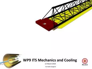
Assembly & Testing NA62 CEDAR Meeting 3May2012
Assembly Frame with Support Tube NA62 CEDAR Meeting 3May2012
Assembly Procedure • The detector will be assembled and tested in Liverpool: • LH half is fully instrumented with optics, cooling and electronics • Cabling within octants and from octants to patch panel • Functional test of electronics • RH half has cooling plates and pipe-work • Thermocouples and photodiodes to measure environment • The assembly frame is mounted and installation tested • The environmental case is fitted and environmental measurements made (light and temperature) • Ship to CERN and install each half of detector, then environmental case and external cabling to patch panels. NA62 CEDAR Meeting 3May2012
Octant Cooling block HV connectors ATEX nitrogen enclosure Quartz lens 90o spherical mirror Support cylinder bolted to CEDAR Lightguide Support Cylinder bolted to CEDAR flange Detector frame NA62 CEDAR Meeting 3May2012
Frame doubles as: Installation frame for detector Support frame for panels comprising Environmental Case NA62 CEDAR Meeting 3May2012
Environmental Cover • Light- and gas-tight • Thermally insulated • Faraday cage • Fire resistant Patch panels Nino HV NA62 CEDAR Meeting 3May2012
Liverpool Assembly Schedule • Assembly Frame with Support Cylinder Complete • Detector Support Frame Complete • ATEX enclosure and Mirror mounts End May • Lightguides and PMT housings Early June • Electronics & Octant wiring Mid June • Cooling panels, chiller & PT100’s Mid June • Detector cabling and patch panels End June • Mechanical installation test End June • Environmental Enclosure Early July • External cabling to EE patch panel Early July • Temporary LED system and System test Mid July • Pack and ship to CERN End July NA62 CEDAR Meeting 3May2012
UK Goals for Technical Run • K+ Identification: measurement of efficiency for K and π • Measure normalisation: Actual light/MC light • Measure shape & distribution of light spot – compare with MC • Thermal Environment • Measure temperature and temperature gradient • Establish operating parameters for Chiller • Assess effectiveness of Monitoring & LED systems • Electronics • PMT rates, saturation, cross talk, time resolution • Trigger, DAQ, links to central control • CEDAR motor control and display • Beam measurement programme NA62 CEDAR Meeting 3May2012