Download
1 / 30
300 likes | 422 Views
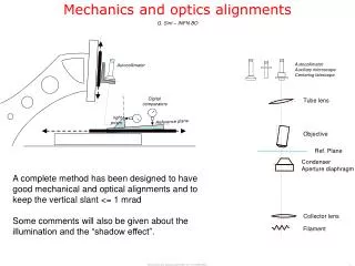
Mechanics and optics alignments. Autocollimator. Digital comparators. right prism. Reference plane. G. Sirri – INFN BO. Autocollimator Auxiliary microscope Centering telescope. Tube lens. Objective. Ref. Plane. Condenser Aperture diaphragm.

E N D
Mechanics and optics alignments Autocollimator Digital comparators rightprism Reference plane G. Sirri – INFN BO Autocollimator Auxiliary microscope Centering telescope Tube lens Objective Ref. Plane Condenser Aperture diaphragm A complete method has been designed to have good mechanical and optical alignments and to keep the vertical slant <= 1 mrad Some comments will also be given about the illumination and the “shadow effect”. Collector lens Filament Mechanics and Optics Alignments - G. Sirri (INFN BO)
Contents Mechanics Reference plane M1. Complanarity Ref. Plane – Horiz. Motion don’t turn the reference plane M2. Perpendic. Ref Plane - Vertical Motion compensate prism systematics Plane parallel window method M3. Parallelism Right angle bracket (stand) - Ref. Plane Comments on mechanical alignments 1. Center the Collector Optics 2. Verify the Revolver position 3. Focus the Condenser (Koehler step 1) 4. Center the Aperture Diaphragm (Koehler step 2) 5. Center and focus the lamp filament Actual lamphouse About the illumination Lamphouse with centering lamp 1. Filament out of center About the shadow effect 2. Vertical stage misalignment 3. “Shadow Effect” from clusters Mechanics and Optics Alignments - G. Sirri (INFN BO)
Reference Plane 10 μm a few fringes per inch 10 cm • The alignment procedure is designed with reference to the upper surface of a plane parallel window ; • This window is produced by Silo (Florence) according to the following specifications: Specifications: THICKNESS TOLERANCE:< 10 μm per 10 cm length PARALLELISM:< 3 arc min (1 mrad) FLATNESS:a few fringes per inch(~400 nm per cm)( local slope < 0.1 mrad) • This window is used to realize the actual vacuum system (Reference Plane = Object Plane) Mechanics and Optics Alignments - G. Sirri (INFN BO)
M1. Complanarity Ref. Plane – Horiz. Motion Micos MS-8 Test both x and y directions ReferencePlane Horiz, MotionPlane Target: less than 10 microns per 10 cm Instruments: digital comparator Adjustment: thin metallic foils between the window frame and the horizontal stage (or screws ?) BO-MIC2 (5 nov 2004) x: 8 µm per 80 mm (0.1 mrad) y: 10 µm per 60 mm (0.2 mrad) BO-MIC1 (8 nov 2004) x: 4 µm per 50 mm (0.1 mrad) y: 8 µm per 50 mm (0.2 mrad) Micos MS-8 Digital comparator 000037 Mechanics and Optics Alignments - G. Sirri (INFN BO)
M2. Perpendic. Ref Plane - Vertical Motion Micos MS-8 Test both sagittal and tangential directions Digital comparator Vert. MotionDirection 000037 prism Reference Plane Target: less than a few microns per 2 cm Instruments: digital comparator, right prism (invert the prism to compensate systematic errors) Adjustment: thin metallic foils between the table and the granite arm or between the granite arm and vertical stage Micos stage BO-MIC2 (5 nov 2004) x: 2 µm per 20 mm (0.1 mrad) y: 8 µm per 20 mm (0.4 mrad) BO-MIC1 (8 nov 2004) x: 2 µm per 20 mm (0.1 mrad) y: 5 µm per 20 mm (0.2 mrad) Micos MS-8 Mechanics and Optics Alignments - G. Sirri (INFN BO)
M3. Parallelism Right angle bracket (stand) - Ref. Plane Target: less than 1 mrad Instruments: autocollimator Adjustment: thin metallic foils between the bracket and the vertical stage (screws in the next generation of brackets ?) Micos MS-8 Micos stage BO-MIC2 (5 nov 2004) x: 2 arc min. (0.6 mrad) y: 2 arc min. (0.6 mrad) BO-MIC1 (8 nov 2004) x: < 2 arc min. (0.6 mrad) y: < 2 arc min. (0.6 mrad) Test both sagittal and tangential directions Autocollimator Right angle bracket (stand) Micos MS-8 Reference Plane Mechanics and Optics Alignments - G. Sirri (INFN BO)
Comments on mechanical alignments After the alignment of the mechanical axes, the optical components must be centered one at a time with the centering telescope. The mechanics should not be moved anymore*. • Unfortunately the global design forces us to remove the reference plane in order to access the condenser • A test has been made (BO-MIC1 15 nov 2004): the reference plane, the horizontal stage and the illumination stand have been completely dismounted and mounted again. The re-positioning is good with an acceptable parallelism (< 0.2 mrad) and doesn’t need to repeat the entire procedure (but it needs 4 good screws for the reference plane! The 3 clamps supplied by MICOS are not enough -- >40 mm in 4 cm). Micos stage Micos MS-8 Mechanics and Optics Alignments - G. Sirri (INFN BO)
Center the Collector • Mount the trinocular tube with the short tube, • Don’t use the frosted glass, the revolver and the condenser, • Open the lamphouse and mask the lamp with an diffusive shield, • Center the collector by moving the illumination stand. Centering telescope Tube lens Ref. Plane • Notes: • The revolver must not be used because it will hide the rim of the collector lens; alternatively a diaphragm or a graticule with concentric circles above the collector lens can be used to find the center; • The field lens and the field diaphragm should be also centered before collector (not simple but not so crucial, thanks to construction tolerance). Illuminationstand Collector lens diffusiveshield Filament Mechanics and Optics Alignments - G. Sirri (INFN BO)
2. Verify the Revolver position • Put the diffusing shield on the reference glass; • Mount the objective • Mount the revolver and verify the alignment of the objective pupil. Centering telescope Tube lens Objective diffusingshield Ref. Plane • Notes: • The revolver mounting is not bi-directional; take care that you respect the reference angle. • The objective centering should be given by mechanical tolerances. However, at this moment it is possible to check the centering of the objective and the differences in the centering of the other mounting holes. Collector lens Filament Mechanics and Optics Alignments - G. Sirri (INFN BO)
3. Focus the Condenser (Koehler step 1) Eyepiece Tube lens Objective • Mount the condenser and the frosted glass; • Put an emulsion on the reference plane; • Focus the objective inside the emulsion sheet; • Close the field diaphragm • Focus the field diaphragm image looking in the eyepieces (or the camera) and moving the condenser up and down; • Afterwards open the field diaphragm until the field of view is fully illuminated. Emulsion Ref. Plane Condenser Aperture diaphram Field diaphragm Frosted glass Collector lens Filament Mechanics and Optics Alignments - G. Sirri (INFN BO)
4. Center the Aperture Diaphragm (Koehler step 2) • Center the aperture diaphragm (and condenser) by centering the field diaphragm image as seen by the eyepieces; or (better solution) • Remove an eyepiece (or the camera) and use the auxiliary microscope; • Center the aperture diaphragm looking the back focal plane of the objective; the aperture diaphragm must be centered with respect to the exit pupil of the objective. Auxiliary microscope Tube lens Objective Ref. Plane Condenser Aperture diaphram • Notes: • Using the first technique, the centering error of the field diaphragm may be compensated by an opposite centering error of the aperture diaphragm (condenser). The procedure is more simple but not so accurate as the second one. Field diaphragm Frosted glass Collector lens Filament Mechanics and Optics Alignments - G. Sirri (INFN BO)
5. Center the lamp filament • Remove the frosted glass; • Put the filament mirrored image out of focus (moving the mirror); • Focus (moving axially) the lamp looking into the auxiliary microscope. The aim is to have a good and homogeneous illumination of the aperture diaphragm; • Move the lamp filament in order to cover the center (one half) of the diaphragm; • Center and focus the filament mirrored image. Auxiliary microscope Tube lens Objective • Notes: • In italic only for lamphouse with the mirror (available in the next generation of illuminators). • This operation should be done also in the case of pre-centered bulbs (it is important because it is connected to the “shadow effect ”). The lamp can be moved a bit with a pressure on its stems. Carrying away the lamp from the collector can increase the dimensions of the light beam on the diaphragm and consequently the diaphragm illumination. Ref. Plane Condenser Aperture diaphram Field diaphragm Frosted glass Collector lens Filament Mechanics and Optics Alignments - G. Sirri (INFN BO)
Comments about the current illumination Remove an eyepiece and look at the exit pupil of the objective where is the image of the aperture diaphragm (better with the auxiliary microscope) • The ideal case is to have an aperture diaphragm which is homogeneously illuminated (which means isotropic illumination of the field of view). • The current illumination is not a perfect Koehler system: • the filament image can be neither centered nor focused; • the filament image doesn’t cover completely the aperture diaphragm. • A strong frosted glass after the collector can act as a patch; but the aperture diaphragm still remains not homogeneously illuminated. The borders are quite dark and eccentric lighter zones can behave as intense unidirectional out-of-axis sources ( in our case can contribute to the “shadow” effect). • Focusing the lamp can increase the resolution • Moving the filament far from the collector can increase the dimensions of the beam and can better cover the diaphragm ( a greater aperture means a better resolution). • Centering the image of the filament still remains difficult and can be done by hand. • A weak frosted glass is not recommended. Lamphouse Mechanics and Optics Alignments - G. Sirri (INFN BO)
Lamphouse with centering filament and back mirror • Nikon Italia is producing a prototypal illumination system with centering and focusing filament.This prototype has been tested with Nikon Italia in Bologna (4 nov 2004). • A spherical mirror generates a full size image of the filament close to the filament itself. This image can be centered and focused too.Doubling the image of the filament will produce a more intense light beam and in particular can give a more homogeneous illumination of the aperture diaphragm. • Several set-up can be used: A. joint images B. adjacent images (square –like) • The frosted glass is recommended. (Otherwise, due to the axial magnification of the collector, the image of the filament could be seen in the field of view) • The “shadow effect” can be corrected with an higher precision than the actual case. Some tests have been done with Nikon Italia. Not ideal case: the image of the filament is obscured by the filament itself and may overheat it. Optimal solution: the two images do not overlap and the general shape may be square Mechanics and Optics Alignments - G. Sirri (INFN BO)
About the “shadow effect” • Commonly, we define the “shadow effect” as the horizontal motion of a mark (or a grain) image during focusing. This effect is negligible in ordinary microscopy (ex. for biology) but in any case it is a symptom of some misalignment. - 50 µm 0 µm +50 µm • The “shadow effect” depends on two factor:(test made at Bologna with Nikon Italia 4 nov 2004) • Something in the illumination system is not centered (filament, collector or condenser); • The motion of the vertical stage is not perpendicular to the reference plane. Mechanics and Optics Alignments - G. Sirri (INFN BO)
1) “Shadow effect” : not-centered filament Z X BO-MIC2 4 nov 2004Lamphouse with centering knobsFilament out of center From the “shadow” : 55 pixel in 100 µm = (0.25 µm/pixel) = 13.8 µm in 100 µm = 138 mrad 100 µm 55 pixel =13.8 µm Mechanics and Optics Alignments - G. Sirri (INFN BO)
2) “Shadow effect” : vertical stage misalignment Z Y BO-MIC2, 4 nov 2004Lamphouse with centering knobsFilament centered; BUT the vertical axis has been tilted ! Direct measure := 70±10 µm over 16 mm (plane parallel window)= 74±1 µm over 16 mm (prism+comparator) = 5 mrad From the “shadow” : = 8 pixel in 100 µm = (0.25 µm/pixel) = 2 µm in 100 µm = 20 mrad (!) 100 µm Can we use shadows to correct quantitatively the misalignment? 8 pixel =2 µm Mechanics and Optics Alignments - G. Sirri (INFN BO)
“Shadow Effect” from clusters … atan( 0.3 *(eX[0] –eX[ncl-1])/(eZ[0]-eZ[ncl-1]) Z (um) atan( 0.3 *(eY[0] –eY[ncl-1])/(eZ[0]-eZ[ncl-1]) X (pixel) Scan of a thin emulsion layer: the grainare reconstructed by connecting the clusters to form a vertical chain. X Preliminary Y Direct measures: BO-MIC1 (8 nov 2004) x: 2 µm per 20 mm (0.1 mrad) y: 5 µm per 20 mm (0.2 mrad) Final Z Slant 1 mrad Preliminary Also in this case the shadows don’t givequantitative indication of misalignments. Mechanics and Optics Alignments - G. Sirri (INFN BO)
Some examples BO MIC3, 30 aug 2004 BO MIC1, 11 nov 2004 inclinazione_asse_mic3_(da -40 um a 90 um ogni 10 um).bmp mic1 041111 1745 (+50 0 -50).bmp 14 images from -40 um to 90 um 3 images at -50 um, 0 um and 50 um In any case the qualitative results are good. Mechanics and Optics Alignments - G. Sirri (INFN BO)
Conclusions • A complete alignment method has been designed. • The method has been tested several times on the Bologna microscopes. • The reference window is the vacuum chamber which we use to keep the emulsion on the stage. Its surface has good planarity features (± 5m). • The single measurements of parallelism, and perpendicularity are good and the measured vertical slant from emulsion sheets are less than 1 mrad . • The method of the plan parallel window seems to be not exact enough to align the vertical motion axis, the digital comparator+prism is a better solution. • The actual lamphouse can be used but the lamp set-up is very crucial. • A lamphouse with centering lamp is surely more simple to be adjusted. • A new prototype of this type of lamphouse produced by Nikon Italia has been tested and can be used. • The “shadow effect” is due to both illumination optics and vertical axis misalignments. • The “shadow” seems not to give quantitative indication of the misalignment. Mechanics and Optics Alignments - G. Sirri (INFN BO)
Step M1 : don’t turn the reference plane ! Mechanics and Optics Alignments - G. Sirri (INFN BO)
M1. Complanarity Ref. Plane – Horiz. Motion ReferencePlane Horiz, MotionPlane What happens if you turn the reference plane… – 1 – The surfaces of the reference plate are parallel; the comparator doesn’t change. The situation is good also in case of bad mounting (as in the picture). Assume that the complanarity is guaranteed.Notice that the Micos clamps are not sufficient to keep steady the reference plane. Micos MS-8 Digital comparator 000037 Mechanics and Optics Alignments - G. Sirri (INFN BO)
M1. Complanarity Ref. Plane – Horiz. Motion ReferencePlane Horiz, MotionPlane What happens if you turn the reference plane… – 2 – The surfaces of the reference plate are NOT parallel. If you turn the reference plane, the parallelism is lost. Micos MS-8 Digital comparator 000037 Mechanics and Optics Alignments - G. Sirri (INFN BO)
Step M2: Turn the prism to compensate systematic errors Mechanics and Optics Alignments - G. Sirri (INFN BO)
M2. Perpendic. Ref Plane - Vertical Motion Digital comparator Vert. MotionDirection 000037 prism Reference Plane What happens if you turn the prism 180° about the vertical axis … -- 1 -- ……………… Micos stage Micos MS-8 Mechanics and Optics Alignments - G. Sirri (INFN BO)
M2. Perpendic. Ref Plane - Vertical Motion Digital comparator Vert. MotionDirection 000037 prism Reference Plane What happens if you turn the prism 180° about the vertical axis … The error in the prism is compensated. -- 2 – ……………………………….. Micos stage Micos MS-8 Mechanics and Optics Alignments - G. Sirri (INFN BO)
Plane parallel window method to align the vertical stage (Step M2) Mechanics and Optics Alignments - G. Sirri (INFN BO)
M2. Perpendic. Ref Plane - Vertical Motion with plane parallel window method Target: less than a few microns per 2 cm Instruments: objective 4x, episcopic illuminator, plane parallel windows with a crosshair and a mirror Adjustment: thin metallic foils between the table and the granite arm or between the granite arm and vertical stage crosshair plan parallelwindow mirror Micos stage Micos MS-8 Vert. MotionDirection plan parallelwindow Reference Plane Mechanics and Optics Alignments - G. Sirri (INFN BO)
M2. Perpendic. Ref Plane - Vertical Motion with plane parallel window method Advantage: • Only one measure to estimate both x and y misalignments (eventually turn the reticule to compensate systematics). Disadvantage: - Expensive (cost of the plan parallel window ?) - Complicated to be mounted (the test must be repeated several times) - Less precise than the prism+digital comparator(the optical resolution of an objective 4/0,1 is about 3 m). Vertical displacement: 16 mmPixel image size ≈ 3 µmResolution ≈ a few pixel (?) ≈ 10 µmAng. Resolution ≈ 1 mrad too large!to be compared with the prism+comparator method: 1 µm over 20 mm (0.05 mrad) Measurements made in Bologna (4 nov 2004) with both method gave similar results (5 mrad tilt): - plane parallel window = 70±10 µm over 16 mm - prism+comparator = 74±1 µm over 16 mm Mechanics and Optics Alignments - G. Sirri (INFN BO)