Download
1 / 31
320 likes | 430 Views
WP9 ITS Mechanics and Cooling. 12 March 2014. Corrado Gargiulo . ITS objectives for 2014 – WP9. Finalization of IB and OB layout IB QM design : Space Frame +Cold Plate, End-Wheel, Cylindrical Structural Shell IB BARREL QM production based on “pad chips”

E N D
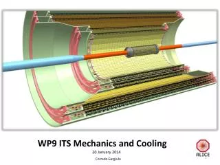
WP9 ITS Mechanics and Cooling 12 March 2014 Corrado Gargiulo
ITS objectives for 2014 – WP9 Finalization of IBand OBlayout IB QM design: Space Frame +Cold Plate, End-Wheel, Cylindrical Structural Shell IB BARREL QM production based on “pad chips” OBQM design: Space Frame, Cold Plate OB STAVE QM production based on “pad chips” … EMEngineeringModule, QualificationModule(finalquality)
ITS objectives for 2014 – WP9 Finalization of IBand OBlayout IB QM design: Space Frame +Cold Plate, End-Wheel, Cylindrical Structural Shell IB BARREL QM production based on “pad chips” OB QM design: Space Frame, Cold Plate OB STAVE QM production based on “pad chips” …
Finalization of IB and OB layout (TDR, endorsed) • BP outer radius19 • Layer 0 mean radius23.38 • Layer 0 inner boundary >21.8 • Middle Layer radius TDR6 / TDR7 • Stave width15+1(FPC) • Stave length (cold plate) IL 320 (4th IB layer) • IL 290=9.6+270.8+9.6 • ML 870= 14.85+840.3+14.85 1066 • OL 1502=15.7+1470.6+15.7 Detectors boundaryradius@ >21.8mm
Beam Pipe NEW DESIGN 19mm OR • Submitted to LEB commitee for approval
ITS VS BP Gap >2.8 mm No change in the ITS layers radius (TDR) R 19,0 19.0
ITS Outer Barrel Baseline TDR 6 TDR 7 Simulation results by the end of March
ITS objectives for 2014 – WP9 Finalization of IB and OB layout IB QM design: Space Frame +Cold Plate, End-Wheel, Cylindrical Structural Shell IB BARREL QM production based on “pad chips” OB QM design: Space Frame, Cold Plate OB STAVE QM production based on “pad chips” …
Inner Barrel FlexPrinted Circuit 9 PIXEL Chip ColdPlate Spaceframe Inner layer stave 300mm length, 1.6 gram weight Polyimide tubes ID 1.024mm; wall thickness 25 micron
IB Carbon spaceframe IB status DEVELOPMENT TEST on EM (Engineering Module) sag • Thermal test OK • Thermoelastic test on going • Stiffnesstest sag <10 µm • Vibrational test >100Hz • Dimensional next 167 Hz next PRODUCTIONQM (FINAL QUALITY) • Production of new spaceframe with high dimensional accuracy • new moulds under production • Production of full barrel (48 staves)
EM IB Carbon spaceframe on going M60J Alternative option under investigation to further improve stiffness and thermo-elastic stability Change of Carbon fleece with K13D2U (same weight) 45µm 20µ Carbon paper 30µ (30µ) 70µ 45µm K13D2U 45µm 20µ 11
QMIB Connectors providestaves position accuracy status DESIGN • 3D, 2D production drawingsOK… …needvalidationfro WP6, needsadditionalconsiderations on surveystrategy next PRODUCTION • 100 CONNECTORS • Design and Production of assemblyjig, to glue the connector to the spaceframe Deisgnmodifiedrespect to TDR to increaseaccuracy
QMIB production Spaceframe+Coldpalte n.48 2014 JULY Tentative schedule
QMIB End-Wheels status DESIGN • 3d, OK… …need further consideration on cable and piping routing next DESIGN • Design and Production of molds for layer assembly
QMIB End-Wheels From Antonello & Antoine
QMIB CYlindricalSupport Structure status DESIGN • 3d, OK… …needs further consideration on survey targets locations and interface with Service Barrel next DESIGN • Design and Production of molds
QMIB production End-Wheels and CYSS 2014 SEPTEMBER
Production site Bldg 167 new … ongoing CERN GS HSE MaterialHazard Fireextinguisher CERN electricalinspection Ventillationsysteminstallation 90m2cleanenvironment, 18-23°C, 50% humidity
Evgeny &Viktor Samuel Yannick Almostthere!
ITS objectives for 2014 – WP9 Finalization of IB and OB layout IB QM design: Space Frame +Cold Plate, End-Wheel, Cylindrical Structural Shell IB BARREL QM production based on “pad chips” OBQM design: Space Frame, Cold Plate OB STAVE QM production based on “pad chips” …
Outer Barrel stave status DEVELOPMENT TEST On spaceframe (Carbon fiber K13 D2U) • Bending test &FEA sag ≈95µm • Vibrationaltest 1st freq=51Hz; dynamicresponseongoing On coldpalte • Thermoelastic test αexp ~ 12 x 10-6 K-1 • Thermal (150 and 300 mW/cm2), hydraulic test Ok • Thermal test on full lengthcoldplatenext next PRODUCTIONQM (FINAL QUALITY) • Production of 1 SPACEFRAME+ 2COLDPLATES • Production of EMs
EM OB Carbon spaceframe on going • Improve stavestiffness • Full k13 spaceframe has shown to be too brittle • N.2 Produced and tested, spaceframe M55j baseline • N.2 Produced and tested, spaceframe M55j with additional layer • N.2 Produced and tested, spaceframe M55j with two layers K13D2U(embedded) 3 point bending test results Confirmedprevious test Lumped mass (test) Distributed mass (derived from test)
EM OB Coldplate • Production of 1 cold plate1,5m/ID=2mm/option-a • Production of 1 coldplate1,5m/ID=2mm/option-b • Production of 1 cold plate 300mm for thermaltest for both option a and b on going • Mould modified (for ID 2mm), Grenoble • New 2mm ID pipes arrived • K13 from Berkley arrived • Option b) Alternative option under investigation to further improve stiffness and thermo-elastic stability • Option a) Baseline 45µm 20µ 30µ 30µ ID=2.67mm, wt=0.065mm ID=2.00mm; wt=0.032mm 90µ 70/45µm 45µm 20µ 24
Spaceframe QMOB SpaceframeCONNECTOR new design New design Removed spring connection between stave and end-wheels x TDR baseline Spring Spring x x Ruby sphere Reference Plane on the End-Wheels
QMOB SpaceframeCONNECTOR revised design status DESIGN • EM 3D, 2D production drawingsOK… … need to be validated by WP7,8 and by test next PRODUCTION • 20 CONNECTORS • Design and Production of assemblyjigneeded to glue the connector to the spaceframe
QMOB ColdPlateCONNECTOR status DESIGN • 3d, 2D production drawingsOK… …needsvalidation by WP7,8 next PRODUCTION • 20 CONNECTORS • Design and Production of assemblyjig, to glue the connector to the spaceframe
EM OB End-Wheels status DESIGN • EM 3d model proposal next DESIGN • EM 3D design
EM OB End-Wheels • Definition of cooling modularity and cooling scheme • Definition of electrical and hydraulic connection layout • DC-DC convertermechanics and cooling 300mm 300mm 300mm P. Kuijer 2014-3-11 300mm DC-DC 150mm EW
ALI-UPGRADE 3D CAD MODEL overall 3D CAD MODEL available on CERN ITS UPGRADE CAD REPOSITORY R1_20140311
Next EM Inner stave & Outer stave -optimize carbon plieslay-up QM Inner stave & QM Outer stave -freezeconnector design and start production -developjigs for connector to spaceframegluing