Download
1 / 30
300 likes | 439 Views
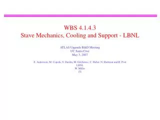
WBS 4.1.4.3 Stave Mechanics, Cooling and Support - LBNL. ATLAS Upgrade R&D Meeting UC Santa Cruz May 3, 2007 E. Anderssen, M. Cepeda, S. Dardin, M. Gilchriese, C. Haber, N. Hartman and R. Post LBNL W. Miller iTi. 1064mm. 71.5mm. Reminder of Concept. Precision mechanical core

E N D
WBS 4.1.4.3Stave Mechanics, Cooling and Support - LBNL ATLAS Upgrade R&D Meeting UC Santa Cruz May 3, 2007 E. Anderssen, M. Cepeda, S. Dardin, M. Gilchriese, C. Haber, N. Hartman and R. Post LBNL W. Miller iTi
1064mm 71.5mm Reminder of Concept • Precision mechanical core • High-modulus facings • Honeycomb • Embedded cooling tube • Squashed(-> for evaporative cooling) • Round with foam for thermal contact(-> CO2 cooling) • Side closeouts(carbon-fiber) and end closeouts(aluminum with supporting pins) Prototype dimensions
FY07 - Accomplished • Extensive presentations – see link at bottom and backup slides • Prototype conceptual design complete and drawing sets for • “7cm” wide mechanical core for both squashed and round tubes – for prototype fabrication underway • “10 cm” wide for round tube – most recent upgrade design. Too late to change prototype fabrication but good for support studies. See backup slides. • Extensive FEA to validate concept (as driven by perceived requirements) • Deflections under gravity load and different support conditions • Thermal properties(T and thermal runaway) • Distortions upon cooldown • Prototype fabrication tooling done • Prototype materials in hand • Facing samples made and tested • First test fabrication assembly made (“foot-long”) • Study of support concepts initiated http://phyweb.lbl.gov/atlaswiki/index.php?title=ATLAS_Upgrade_R%26D_-_Mechanical_Studies
Mechanical Core Weight/Design • Approximate weights of sample shown below • Note no end closeouts on this assembly trial prototype • Designed for very high stiffness, end supports • If had multiple supports, reduced stiffness requirement… • Eliminate honeycomb and epoxy -14% • Eliminate side closeouts+epoxy -13% • Need a bit of something in addition to tube to keep facings parallel • Reduce facing thickness to minimum for heat conduction and stability after cooldown – estimate in progress………..
FY07 – Plan Stave Mechanical Core • Plus design effort (eg. minimize weight) coupled with support concepts
FY07 – Support of Staves • Support options • For staves at mean radii of: 380, 490, and 600mm. About 2m long. • Based on 10cm wide by 10cm long silicon modules mounted on a stave constructed of composite material with embedded cooling ie. current concept • FEA for end plate geometry • FEA solutions for cylindrical shell geometry. • Single shell with external rings • Single shell with external and internal rings • Space frame shell-like structure with rings • Work through multiple options relatively quickly • Feedback into stave design • Headed toward integrated design
Example Barrel Structures- Disk Primary • Disk Support Structure • Stave, 1m long supported at ends, hopefully with near “fixed end condition” • Disks are sandwich structure, high modulus composite facings with HC core • Inserts in HC to provide registration points for precision locating pins • Outer and Inner composite shells, single layer to stabilize disks • Outer shell connects to outermost silicon layers at their “disk planes” of suspension Staves slide in place, retained by plates located with pins
Example Barrel Structures- Disk Primary • FEA of Disk Frame Supports • Structure 2m long with two end plates and one mid-span plate • Outer and inner shells are 1mm thick • End plates are constructed as a sandwich • Number of staves in circumference, 23, 32, and 36 • Total in 2m length 186 • Mass estimate for FEA 125.2kg • 155997 elements and 107421 nodes • Allowed definition of slots for staves
Example Barrel Structures- Disk Primary • Structure Description-2m long with 1m staves • Outer shell 1.4m diameter, 1mm thick M55J quasi lay-up • Inner shell 0.46m, same as outer • End plates M55J facings 0.5mm thick, with 1.27cm thick HC core • Mass of structure 27.74kg • Mass of 186 staves=125.2kg • Gravity sag • Mid-plate region ~12µm • Out-of-plane distortion of end plates <0.5µm Four localized points at mid-plane of the plates on the end—very simplistic Some modal analysis in backup slides
Example Barrel Structures- Shell Primary • Shell Concept • Potentially supports two stave layers • Locating features in mounting rings are machined in one set-up • Rings are inserted over shell and held in place with alignment fixture during bonding to shell • 1m Stave Assembly • Stave mounts from end, engaging alignment pins in rings • Staves meet at center, locked at this point Locating pins in rings Light weight composite sandwich rings
Stave Support Concept-10cm Wide Module • Shell Concept: Single layer • Avoid sandwich construction complexity • Shell stiffness enhanced with radial rings • Staves are mounted to rings • Five rings chosen for 2m shell design • Provides a mid-span support for stave • Rings although sandwich members are modeled as single thickness laminate • Concept offers potential for supporting two detector layers • Could conceive of half-shells, although adds complexity but easier to mount staves Mean shell radius 595cm
FEA of Support Options- Single Shell • Example #1---One Silicon Layer • 0.5mm thick composite, ring reinforced shell, 2m long at radius of 595mm • Rings used as primary support for 1m staves, 38 staves for a total of 76 to make 2m length • Mass of support shell and outer rings 6.64kg • Rings as modeled are 5cm deep, 1mm thick facings • From a practical sense the rings would be constructed as a sandwich, whereas the shell is not • Mass of 76 staves is ~51.15kg • Deflection at highest point of the rings is < 30microns Max sag at rings <30microns Composite: M55J fiber/cyanate ester resin, 60% fiber fraction ρ=1.64g/cc Shell support: simple constraint, mid-plane at four corners
FEA of Support Options- Single Shell-Two Layers • Example #1---Two Silicon Layers • 0.5mm thick composite, ring reinforced shell, 2m long at radius of 595mm • Added inner rings, 5cm depth, same as outer • Mass of support shell and outer rings 7.98kg • Inner surface has 64 staves to populate 2m, whereas the outer was 76 • Total stave mass ~94.2kg • Deflection at highest point of the rings is < 14microns • Inner rings increased total stiffness significantly • Without inner staves, but with outer staves the deflection is <8 microns Max sag at rings <14microns Total mass: structure plus staves 102.2kg
FEA of Support Options- Flat Panel • Example #2-Flat Panel Construction • Flat sandwich panels are bonded together; ring reinforcements are used for stave attachment • Basic concept used in ATLAS pixel detector • Flat panels used 250micron M55J composite facings with a 6.35mm HC core • Panels have cut-outs to reduce mass • This is an area that can be improved • Structure mass=7.65kg, supporting stave mass of 51.2kg Maximum sag of rings where upper and lower stave attach is 19microns Mean structure radius=595mm
1st Order Summary of Stave Supports • Disk design • Assembly can be tricky, considering stave length and associated services • Stave must pass thru a slot and engage alignment pins at Z=0 • Choice of which end to fix the stave against movement is not clear • Z= 0 might still be a possibility, but is a detail to be resolved • Preliminary Solution of Disk Support is complete • Carries first three of the layers so structure is heavier than other examples • Quite likely that the shells used to support the end plates can be light-weighted • More analysis is needed • Shell (including flat-panel frame) design with rings • Looks quite practical structurally • Mounting of staves on external rings looks practical and quite accessible • 1m staves would be fixed at Z=0, allowing free expansion or contraction in both directions • Mounting of staves inside a shell is more difficult • Light weighting cut-outs could provide the necessary access. Half-shells? • Again fix the staves at Z=0
FY07-FY08 Goals • FY07 • Stave conceptual design validated by FEA DONE • Detailed fabrication design DONE • Fabricate prototypes IN PROGRESS • Support concepts/update mech. core design JUST STARTED • Review preparation TBD • Most critical information now from more prototypes, particularly prototype with silicon and review of requirements that influence design(operating temperature, overlap, replacement, stereo,…..) • Need review end FY07 – early FY08(whenever have results or run out of time) to narrow options before doing more detailed stave design. • FY08 • Refine all aspects of stave design, including preliminary production plan • Build at least 3 full-length prototypes, instrument with silicon and test • Concentrate effort on stave support (ideally one concept) and start to address integration(services) aspects at conceptual level
FY08 - Deliverables • Review materials(documents, presentations) for anticipated collaboration-wide review early FY08 • Stave mechanical core • Revised design based on collaboration-selected “baseline” detectors and electronics(ABCD-N) • Prototype fabrication drawings • Prototype fabrication tooling drawings and tooling • Materials for prototype fabrication • Fabrication of at least three 1m-long cores for use by the collaboration • Mechanical and thermal test results • Support structure • Conceptual design of preferred option for ~2m long barrel structure • FEA and other calculations to demonstrate feasibility of preferred option • Conceptual review of primary interfaces and services (based on SCT and pixel experience) • Review materials in anticipation of collaboration-wide review
FY08 - Budget • Note that this DOES NOT include any work on cooling fittings and related development, which ideally should be included in the design early in FY08 • Minimal effort towards end of FY08 on services integration eg. all the other stuff(cooling, cables, fibers) that has to be attached at ends in any design. Ideally this would come earlier in program but would substantially increase engineering costs.
Looking Ahead to FY09 • Staves • Depends critically on decisions by collaboration, which in turn depends (or should) critically on results from prototypes. • Integrated stave or individual modules • Individual modules(bolted) on stave-like structures • Disks? • Support structures • Layout dependent. Not just integrated stave vs individual modules but also 2m structure or 2m+4m structure • If staves, somewhat independent of stave type although obviously details of mounting depend on stave structure • Would be really good to make full-scale prototype(for 2m length) by end FY09 to validate design and as input to industrial or other production. • In my opinion, mixed production, partly industrial and partly at Lab will be the way to go. • Could make prototype with ID < 1.2m at LBNL for any option
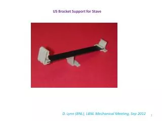
Assembly Prototype Fabrication CN60 facings – assembly prototype CDF bus cable bonded to one face
10cm Silicon Module Stave FEA Parameters Stave length ~1074mm, overall mass ~0.67kg. To be updated based on prototypes
Stave Summary (Data for 6cm Module) • Description: 1m Stave, K13D2U 4/1 fiber Orientation, 4.6mm core height, graphite fiber HC, semi-flatten Al tube (12mil wall, U-Tube shape), Al end caps, steel pins • Gravity sag (FEA) • Purely horizontal and vertical : 55.5µm and 3.5µm respectively • Thermal • Without leakage current heating: average module -17 to -17.8ºC, electronic chips -15.5ºC with -25ºC coolant. Sensor about 3oC warmer with nominal leakage current. • Thermal strain 5µm out-of-plane: 50ºC temperature change plus 0.5W per chip • Thermal strain 6.2µm out-of-plane: 60ºC temperature change only • Coolant Tube Pressure • 4.6mm semi-flat tube: 1.5µm out-of-plane for 100psi (6.9bar C3F8) • For CO2 use small diameter round tube, deflections and stresses become non-issue
Stave Summary (10cm Module) • Thermal solutions (no structural FEA as yet) • Description: 10 chips 0.5W each, same facings and essentially same hybrid dimensions • Initial question: how to cover wide transverse heated span using same inside HC core height (4.6mm) • Small diameter tube (2.8mm) with POCO Foam saddle to accept heat from facings— effectively removes the heat • 10W per 2.5cm long module: Single U-Tube module surface temp of -14.5ºC and Triple U-Tube is -17ºC • 10W per 2.5cm long module: Thermal runaway not a problem in either case, 9ºC “head-room” for Single U-Tube and 19ºC for Triple U-Tube • More work needed for 10cm wide stave design • If CO2, then current tube and saddle design OK, if C3F8 then re-visit tube size (reduce thickness of saddle slightly) • Look into thermal strains and gravity sag- do not anticipate problems
Thermal Runaway in 10cm Module • Thermal Runaway Issue: Leakage Current Induced • One of geometry, material conductivities, material thickness, etc. • Strongly influenced by span from outermost point on module to point of cooling • Also, affected by heat load from chips imposed on detector Two cooling options for 10cm wide stave model
Thermal Stability Solutions • Solutions for: • Two geometries • Two leakage current values (conventionally referenced to 0ºC) • Results for stave with embedded cooling tube, single U-Tube or Triple U-Tube • No apparent problem, particularly based on leakage data considered to be most likely to be experienced in SLHC Single U-tube Triple U-Tube
Thermal Runaway Conclusions • Triple U-Tube • Could use C3F8 with considerable safety margin, head-room 19.6ºC using -25ºC cooling fluid temperature • Single U-Tube • Use of C3F8 at -25ºC a bit more problematic, even still the head-room is 9ºC • In short • If a need exists for uniform module surface temperature at or below -25ºC for reasons other than suppressing thermal runaway, then • one should consider the CO2 alternative coolant • -40ºC bulk inlet for the Single U-Tube • -35ºC bulk inlet for the Triple U-Tube
Example Barrel Structures- Disk Primary • Gravity sag along shell axis • Provides measure of first mode due to end plate diaphragm • Deflection of 1.51mm leads to 12.8Hz • Modal analysis • Modal FEA yielded 15Hz for first mode, and 39.44Hz and 39.62Hz for the second and third modes respectively • All modes are plate out-of-plane bending • Increasing face plate thickness to 1mm--- • Increases the frequencies to 18.87, 49.83, and 50.6Hz respectively 1G Deflection in Z 15HZ
Example Barrel Structures- Disk Primary • 2nd Structural changes • Increased facings thickness for end plates to 1mm and the core height to 1.905cm (0.75in) • Raised first mode from 15Hz to 24.9Hz • Second and third modal frequencies are 66.11Hz and 66.77Hz • Possible additional core height might be prudent or internal ribs • Dynamic performance gain versus unfortunate increase in radiation length • Hitting right combination of changes will take more solutions • Suggest adding radial ribs to outside end plate, if space between exiting services allow • Need added material depth