Download

1 / 25
250 likes | 417 Views
Integrated Stave Electrical/Mechanics/Cooling Update. March 6, 2008. Prototypes and Designs. 60 cm, 9 cm strip, 6 segments/side. Stave-06. 1 meter, 3 cm strip, 30 segments/side 192 Watts (ABCD chip), ~2.4 % Xo + support structure. 6 x 3 cm, 6 chips wide. Stave-07. Build and test. Study.

E N D
Integrated StaveElectrical/Mechanics/Cooling Update March 6, 2008
Prototypes and Designs 60 cm, 9 cm strip, 6 segments/side Stave-06 1 meter, 3 cm strip, 30 segments/side 192 Watts (ABCD chip), ~2.4 % Xo + support structure 6 x 3 cm, 6 chips wide Stave-07 Build and test Study 1 meter, 2.5 cm strip, 40 segments/side 200-250 Watts (@0.25 W/chip) ~1.9 – 2.2 % Xo + support 10 x 10 cm, 10 chips wide Stave-08
Introduction • With regard to the Single Sided approach, the arguments about simplicity, material, and cost, have been presented already. • This effort is tightly coupled to the alternative powering efforts, in particular serial, but we would hope to include aspects of DC-DC as well, in the future. • We are concerned that in a large, for example, serial system, grounding, shielding, and modularity issues may be critical • Our goal, therefore, is to build and test a realistic scale system early-on, and include enough options and flexibility to be useful. • With regards to the above, and also to assembly and production issues, we want to confront as much of the full problem as possible, now.
Aspects • Status overview • Components • Fixtures • Electrical testing • Additional critical tests • Alternatives
Issues From Valencia • Progress on testing and fabrication of Stave-07 • Irradiation of hybrids glued directly on silicon surface • Thermal performance of bridged hybrid • Planning for Spring 2008 module review
Status Overview • Central goal is assembly and test of Stave-2007. Confront assembly, test, and measurement issues relevant to future • Have built ~30 hybrids , and operated 5 in a serial chain with good performance • Have built and are studying 4 modules with hybrid on the silicon and 1 “reference” module with hybrid off the silicon • Effort on gluing and alignment procedures implicit in module building • Bus cable has been fabricated • Extra clock lines have been added to allow options for clock distribution included 1 clock for 30 module or 1 clock for 10 modules • All components required to build Stave-2007 are in-hand. • Bridged hybrid has been further simulated and clarified • Irradiation plans underway
Components • 3 cm p-in-n sensors based upon ATLAS-98 • Fanouts – from SCT • 6 ABCD chip, serial powered ceramic hybrid • Approx 30 built and tested with good yield • Stave mechanical core • Ready and waiting • Assembly fixtures • In use • Interface pc boards • Bus cable fabrication complete, delivered • DAQ system (NI-PXI card + LV software) • Power supplies
6 ABCD BeO Ceramic Hybrid • ~30 fabricated and tested • Yield is (surprisingly) good! • Represents a density maxima • Includes HV-GND options within serial scheme • Analog performance is right-on-target • Ceramic flatness is engineered by printing but not perfect. Analog current Ground layer Analog power Power layer Digital power LVDS section Serial power section
Hybrid HV-GND options AC gnd AG-MOD HV Gnd HV in AV-MOD
Module Assembly and Test Fixture Evolve asingle fixture for assembly, bonding, inspection, and test.
Bus Cable Signal Layout Data Readout 1/hybrid Clock & Command lines Port Card HV distribution Serial current return Serial current link
Bus Cable: Shielding Al foil, 50 um thick, can be grounded to each hybrid
HV Supply for 30 step serial system • GENH 150-5 • 0-150 V • 0-5 A • Constant current or constant voltage mode • 30 step ABCD system will require ~120 V and 0.75 A. • Supply is in-hand, preparing to test using hybrid test board daisy chain and then bus cable
Electrical testing • Hybrid performance • verified • Serial powering with increasing drops • 5 OK, new supply allows full 30 drop test • Data transmission in a multi-drop system • 5 test board system OK, now confront full bus cable, Santa Cruz • Module performance • In progress, see slides • Grounding and shielding on a stave • upcoming • Effect of glue • Radiation effects
Module Performance • Reference module (hybrid off silicon) shows excellent performance, low leakage, low noise, and correct gain • Assembly of 4 “hybrid-on” modules has been a learning curve and not without incident • One module shows good leakage and analog performance while the others have larger currents. • Adopting additional safeguards and procedures in order to control performance. • Note – for Stave-06 multiple good “glued-on” modules were built and characterized ref Glued on Input noise @ 2fc
continued Glued on Ref
Additional Critical Tests • Glue studies • Once we get the module assembly process under-control, plan a systematic glue testing program • Temperature cycling • Load with thermal filler (BN) • … • Needs to be repeated on n-in-p sensors as well. • Irradiations • See slides • Bridged hybrid • See slides
Irradiation plans • Irradiations are in planning phase both at BNL and LBNL • BNL is looking at BNL, Boston, and Los Alamos sites • LBNL would use on-site 55 MeV protons • Hope to have first runs in the next few months • A key set of questions here are what would constitute a meaningful measurement? • Conditions • Particle type • Specifics of detector design • One point of view holds this to be purely a surface issue which could be addressed with a gamma source…opinions? • Ultimate skepticism? • Note: CDF and D0 have run with glued hybrids for >5 years
Alternatives • The bridged hybrid has always been the ATLAS preference • FEA indicates reasonable performance for this alternative • However the ultimate material reduction would come from reducing the hybrid substrate even more • A kapton flex or other thin film hybrid with essentially no substrate, glued directly on the silicon, would minimize material • We are not wed to the ceramic technology – it was convenient and low risk for us. • We would be happy to see others pick this challenge up and move it forward! • Since the 6 chip serial hybrid is known to work electrically, we are importing the layout into a fine-pitch printed board design which could be adopted for flex or other etched approaches. We can make this available to the community.
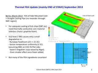
FEA Models of Bridged Hybrid - I • Since the Valencia meeting we have completed FEA analysis of basic thermal performance with bridged hybrid • Multiple models to achieve reliability and understanding • ¼ simple model, similar to ANSYS model by others, air treated as “solid” under bridge • ½ model with air box to allow for 3D air effects (not just under bridge), no air flow Air box for 1/2 ¼ model ½ model Air gap
FEA Models of Bridged Hybrid -II • Multi-hybrid model, with air flow included(so far 0.01 m/sec) • For simplicity, all studies so far done with tube wall temperature fixed at -28C, 0.25 W/IC and no detector heating. • Goal is to compare first with glued hybrid under same conditions • More details are here and here Multi-hybrid model
Short Summary • Good agreement among models • Modest effect of gas flow • Reduced K means lower than nominal K in structure. No optimization of structure yet • For comparison, nominal design (hybrids glued on silicon) for comparable assumptions yields max sensor temperature of about -22.5C
Conclusions • Focused attempt to address the plans and issues discussed in Valencia • All components for Stave-2007 are in-hand • Approach is friendly to alternatives – bridges etc • We welcome the participation, input, or suggestions of the community • Look forward to preparing for the June review