Download
1 / 30
300 likes | 481 Views
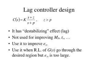
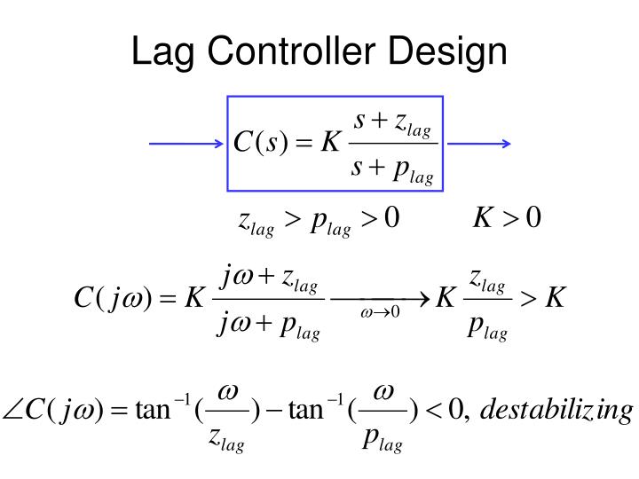
Lag Controller Design. z/p=40. z/p=20. z/p=10. z = w gcd /5. w gcd. z/p=5. Kill PM by 10 to 12 deg. z/p=40. z/p=20. z/p=10. z = w gcd /10. w gcd. z/p=5. Kill PM by 5 to 7 deg. z/p=40. Want these: DC gain boosting. z/p=20. z/p=10. z = w gcd /20. z/p=5. w gcd.

E N D
z/p=40 z/p=20 z/p=10 z=wgcd/5 wgcd z/p=5 Kill PM by 10 to 12 deg
z/p=40 z/p=20 z/p=10 z=wgcd/10 wgcd z/p=5 Kill PM by 5 to 7 deg
z/p=40 Want these: DC gain boosting z/p=20 z/p=10 z=wgcd/20 z/p=5 wgcd Don’t want these: PM reduction! Kill PM by 2 to 3 deg
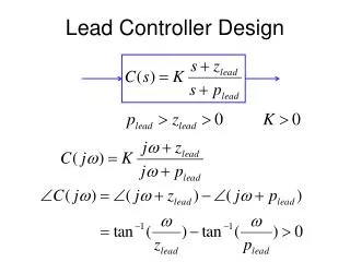
Lag and lead-lag Design Steps • From plant, draw Bode plot • From specs => PMd and wgcd • If there is speed or BW req, wgcd, • In this case, if PM not enough, design PD or lead • Otherwise, choose wgcd to have PM>PMd • Find K to enforce wgcd: • Find Kp,v,a-have with K and C above • Find Kp,v,a-des from ess specs • zlag/plag = Kp,v,a-des/Kp,v,a-have • Let zlag= wgcd/5~20, depending on PM room • Compute plag
Lag design example • Plant transfer function is given by: • Desired design specifications are: • Step response overshoot <= 10% • Steady state tracking error to ramp input is <=0.01 Note: no speed or BW requirement, so just choose wgcd to have enough PM
n=[1]; d=[1/5/50 1/5+1/50 1 0]; figure(1); clf; margin(n,d); %proportional control design: figure(1); hold on; grid; V=axis; Mp = 10/100; zeta = sqrt((log(Mp))^2/(pi^2+(log(Mp))^2)); PMd = zeta * 100 + 3; semilogx(V(1:2), [PMd-180 PMd-180],':r'); %get desired w_gc x=ginput(1); w_gcd = x(1); K = 1/abs(polyval(n,j*w_gcd)/polyval(d,j*w_gcd)); Kva = K*n(end)/d(end-1); ess=0.01; Kvd=1/ess; z = w_gcd/5; p = z/(Kvd/Kva); ngc = conv(n, Kp*[1 z]); dgc = conv(d, [1 p]); figure(1); hold on; margin(ngc,dgc); [ncl,dcl]=feedback(ngc,dgc,1,1); figure(2); step(ncl,dcl); grid; figure(3); margin(ncl*1.414,dcl); grid;
n=[1]; d=[1/5/50 1/5+1/50 1 0]; figure(1); clf; margin(n,d); hold on; grid; V=axis; Mp = 10/100; zeta = sqrt((log(Mp))^2/(pi^2+(log(Mp))^2)); PMd = zeta * 100 + 3; semilogx(V(1:2), [PMd-180 PMd-180],':r'); x=ginput(1); w_gcd = x(1); %get desired w_gc K = 1/abs(polyval(n,j*w_gcd)/polyval(d,j*w_gcd)); Kva = K*n(end)/d(end-1); ess=0.01; Kvd=1/ess; z = w_gcd/10; p = z/(Kvd/Kva); ngc = conv(n, K*[1 z]); dgc = conv(d, [1 p]); figure(1); hold on; margin(ngc,dgc); [ncl,dcl]=feedback(ngc,dgc,1,1); figure(2);step(ncl,dcl); grid; figure(3); margin(ncl*1.414,dcl); grid;
clear all; n=[1]; d=[1/5/50 1/5+1/50 1 0]; figure(1); clf; margin(n,d); grid; V=axis; hold on; Mp = 10/100; zeta =sqrt((log(Mp))^2/(pi^2+(log(Mp))^2)); PMd = zeta * 100 + 7; semilogx(V(1:2), [PMd-180 PMd-180],':r'); x=ginput(1); w_gcd = x(1); %get desired w_gc K = 1/abs(polyval(n,j*w_gcd)/polyval(d,j*w_gcd)); Kva = K*n(end)/d(end-1); ess=0.01; Kvd=1/ess; z = w_gcd/10; p = z/(Kvd/Kva); ngc = conv(n, K*[1 z]); dgc = conv(d, [1 p]); figure(1); hold on; margin(ngc,dgc); [ncl,dcl]=feedback(ngc,dgc,1,1); figure(2);step(ncl,dcl); grid; figure(3); margin(ncl*1.414,dcl); grid;
Lead-Lag design example • Plant transfer function is given by: • Desired design specifications are: • Step response overshoot <= 16% • Step response rise time <= 2 sec • Steady state tracking error to unit acceleration input is <=1 Note: we have all three types of specs: speed, relative stability, and tracking
Strategy • First do a lead design to fix speed and overshoot requirement • Then do a lag design to fix the ess.
n=[1]; d=[1 5 0 0]; figure(1); clf; margin(n,d); grid; hold on; Mp=16/100; zeta = sqrt((log(Mp))^2/(pi^2+(log(Mp))^2)); PMd = zeta * 100 + 5; tr = 2; wn = 1.8/tr; w_gcd = wn*0.8; PM = pi+angle(polyval(n,j*w_gcd)/polyval(d,j*w_gcd)); phimax = PMd*pi/180-PM; alpha=(1+sin(phimax))/(1-sin(phimax)); zlead=w_gcd/sqrt(alpha); plead=w_gcd*sqrt(alpha); K=sqrt(alpha)/(abs(evalfr(tf(n,d),j*w_gcd))); ngc = conv(n, K*[1 zlead]); dgc = conv(d, [1 plead]); figure(1); margin(ngc,dgc); [ncl,dcl]=feedback(ngc,dgc,1,1); figure(2); step(ncl,dcl); grid; figure(3); margin(ncl*1.414,dcl); grid;
Overshoot is too large. Plus, we know the lag controller will further deteriorate Mp. So, redesign for better Mp.
About 12% overshoot. So, let’s go ahead with lag design.
Kaa = ngc(end)/dgc(end-2); ess=1; Kad=1/ess; zlag = w_gcd/20; plag = zlag/(Kad/Kaa); ngcc = conv(ngc, [1 zlag]); dgcc = conv(dgc, [1 plag]); figure(1); margin(ngcc,dgcc); [ncl,dcl]=feedback(ngcc,dgcc,1,1); figure(4); step(ncl,dcl); grid; figure(5); margin(ncl*1.414,dcl); grid; We don’t have too much room to spare for Mp, so choose 20 so that the lag controller only kills about 3 degrees of PM.