PI Controller Design
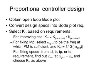
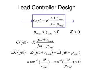
PI Controller Design. Use PI only when you have to increase system type, i.e., when you have to make a nonzero ess to zero!. KI/KP=1/2. KI/KP=1/5. KI/KP=1/10. Want these: DC gain boosting. KI/KP=1/20. w gcd. KI/KP=1/40. -5.7. -1.4. -2.8. -11.3. -26. 6. Don’t want these:

PI Controller Design
E N D
Presentation Transcript
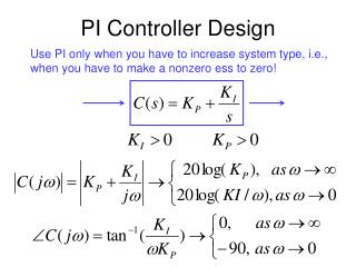
PI Controller Design Use PI only when you have to increase system type, i.e., when you have to make a nonzero ess to zero!
KI/KP=1/2 KI/KP=1/5 KI/KP=1/10 Want these: DC gain boosting KI/KP=1/20 wgcd KI/KP=1/40 -5.7 -1.4 -2.8 -11.3 -26. 6 Don’t want these: PM reduction! Kill PM significantly
Basic PI Design Steps • From plant, draw Bode plot • From specs => PMd and wgcd • If there is speed or BW req, wgcd, • In this case, if PM not enough, design PD or lead • Otherwise, choose wgcd to have PM>PMd • Find K to enforce wgcd: • Let KP = K • And KI = Kwgcd/10~20, depending on extra PM room to spare Need to increase type to make a nonzero ess to be zero. But no requirement on ess after type increase.
Example Want Mp <= 16% Steady state error = 0 when input is constant. Analysis: steady state error = 0 when input is constant means that ess to step must be 0; or the system type must be 1 or higher. Original system is type 0, so need PI control to increase the system type to 1.
%PI control example n=[500]; d=[1 6 5]; figure(1); clf; margin(n,d); hold on; grid; V=axis; Mp = 16; PMd = 70 - Mp +10; %put in a large extra PM, because PI kills PM semilogx(V(1:2),[PMd-180 PMd-180],':r');%draw PMd line x=ginput(1); w_gcd = x(1); %get desired w_gc KP = 1/abs(polyval(n,j*w_gcd)/polyval(d,j*w_gcd)); z = w_gcd/10; KI = z*KP; ngc = conv(n, [KP KI]); dgc = conv(d, [1 0]); figure(1); margin(ngc,dgc); grid; [ncl,dcl]=feedback(ngc,dgc,1,1); figure(2);step(ncl,dcl); grid; figure(3); margin(ncl*1.414,dcl); grid;
Ess is 0 Can afford more overshoot!
Sluggish settling is typical of PI or lag controlled systems. Can reduce it by moving the p/z of controller to higher frequency.
%PI control example n=[500]; d=[1 6 5]; figure(1); clf; margin(n,d); hold on; grid; V=axis; Mp = 16; PMd = 70 - Mp +10; %put in a large extra PM, because PI kills PM semilogx(V(1:2),[PMd-180 PMd-180],':r');%draw PMd line x=ginput(1); w_gcd = x(1); %get desired w_gc KP = 1/abs(polyval(n,j*w_gcd)/polyval(d,j*w_gcd)); z = w_gcd/5; KI = z*KP; ngc = conv(n, [KP KI]); dgc = conv(d, [1 0]); figure(1); margin(ngc,dgc); grid; [ncl,dcl]=feedback(ngc,dgc,1,1); figure(2);step(ncl,dcl); grid; figure(3); margin(ncl*1.414,dcl); grid;
PI Design with ess specs • From plant, draw Bode plot • From specs => Kv,a-des, PMd and wgcd • For required ess, Kv,a-des =1/ess • With C(s)=1/s, compute Kv,a-have • If there is speed or BW req, wgcd, • In this case, if PM not enough, design PD or lead • Otherwise, choose wgcd to have PM>PMd • Find K to enforce wgcd: • Let KP = K, KIdes= Kv,a-des/Kv,a-have • If KIdes <= Kwgcd/5~20, done, let KI = KIdes • Else, increase wgcd and go back to previous step Need to increase type by 1 to make a nonzero ess to be zero, and after type increase, there is further requirement on ess.
Example Want Mp <= 16% Steady state error <= 0.1 for ramp input. Analysis: steady state error <= 0.1 for ramp implies that the system type must be 1 or higher. Original system is type 0, so need PI control. Ess to ramp <= 0.1 requires Kvd >= 10. Previous design leaves Kv = KI*500/5 = 100KI = 4.44 KI=0.0444
In the previous design, KI=0.0444 is already at the maximum of the range Kwgcd/5~20, But KIdes = 0.1, which is a factor of 10/4.22 larger. So need to increase KP. Hence, try letting KI = KIdes = 0.1, and make KP larger by 10/4.22.
Old KI, new KI KP = KP*0.1/KI; KI =0.1; ngc = conv(n, [KP KI]); dgc = conv(d, [1 0]); figure(1); margin(ngc,dgc); grid; [ncl,dcl]=feedback(ngc,dgc,1,1); figure(2);step(ncl,dcl); grid; figure(3); step(ncl,[dcl 0]); grid; Ramp response
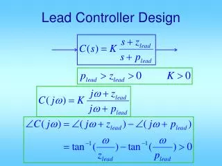
PI Design with PD Design Steps • From required ess, Kv,a-des =1/ess • With C(s)=1/s, compute Kv,a-have • Let KI = Kv,a-des/Kv,a-have • Multiply G(s) by KI/s • Do a PD design for KIG(s)/s, with DC gain=1: • Find wgc and PM • Find PMd • Let f = PMd – PM + (a few degrees) • Compute TD = tan(f)/wgcd • KP = KI*TD
%Alternative PI control by PD design clear all; n=[0 0 500]; d=[1 6 5]; ess2ramp = 0.1; Kvd = 1/ess2ramp; Kva = n(end)/d(end); %after introducing 1/s KI = Kvd/Kva; %multiplying G(s) by KI/s and get new Bode ni=KI*n; di=[d 0]; figure(1); clf; margin(ni,di); hold on; grid; [GM,PM,wpc,wgc]=margin(ni,di); PMd=50+10; phi = (PMd-PM)*pi/180; Td = tan(phi)/wgc; KP=KI*Td; ngc = conv(n, [KP KI]); dgc=di; figure(1); margin(n,d); margin(ngc,dgc); [ncl,dcl]=feedback(ngc,dgc,1,1); figure(3);step(ncl,dcl); grid;
clear all; n=[0 0 500]; d=[1 6 5]; ess2ramp = 0.1; Kvd = 1/ess2ramp; Kva = n(end)/d(end); %after introducing 1/s KI = Kvd/Kva; %multiplying G(s) by KI/s and get new Bode ni=KI*n; di=[d 0]; figure(1); clf; margin(ni,di); hold on; grid; [GM,PM,wpc,wgc]=margin(ni,di); PMd=50+3; phi = (PMd-PM)*pi/180; Td = tan(phi)/wgc; KP=KI*Td; ngc = conv(n, [KP KI]); dgc=di; figure(1); margin(n,d); margin(ngc,dgc); [ncl,dcl]=feedback(ngc,dgc,1,1); figure(3);step(ncl,dcl); grid;
Alternative PI Design Steps • For required ess, Kv,a-des =1/ess • With C(s)=1/s, compute Kv,a-have • Let KI = Kv,a-des/Kv,a-have • Rewrite char eq: (KP + KI/s)G(s) + 1=0 • KP*n/d + KI*n/d/s +1 = 0 • KP *n*s + KI*n+d*s =0, KP*n*s/(KI*n+d*s) + 1 =0 • So do a KP design for n*s/(KI*n+d*s), with KI above • Draw Bode plot for n*s/(KI*n+d*s) • Select max PM frequency • Compute KP to make that frequency wgc
%Alternative PI control example clear all; n=[0 0 500]; d=[1 6 5]; %note same length ess2ramp = 0.1; Kvd = 1/ess2ramp; Kva = n(end)/d(end); %after introducing 1/s KI = Kvd/Kva; %get TF after closing the G(s) and KI/s loop ni=[n 0]; di=[d 0]+KI*[0 n]; figure(1); clf; margin(ni,di); grid; x=ginput(1); w_gcd = x(1); %get desired w_gc KP = 1/abs(polyval(ni,j*w_gcd)/polyval(di,j*w_gcd)); ngc = conv(n, [KP KI]); dgc = conv(d, [1 0]); figure(2); margin(n,d); hold on; margin(ngc,dgc); [ncl,dcl]=feedback(ngc,dgc,1,1); figure(3);step(ncl,dcl); grid;
We conclude that it is impossible to meet the specifications with a PI controller. But we can fix the excessive overshoot with a lead.
Want Mp <= 16% Steady state error <= 0.1 for ramp input. • Overall design: • Ess2ramp <=0.1, PI with KI=1/0.1*5/500=0.1 • Close the I-loop and select KP for best PM shape, KP = 0.084 • Use a lead controller with DC gain = 1 to reduce Mp from 30% to <= 16%
clear all; n=[0 0 500]; d=[1 6 5]; ess2ramp = 0.1; Kvd = 1/ess2ramp; Kva = n(end)/d(end); %after introducing 1/s KI = Kvd/Kva; %get TF after closing the G(s) and KI/s loop ni=[n 0]; di=[d 0]+KI*[0 n]; figure(1); clf; margin(ni,di); grid; x=ginput(1); w_gcd = x(1); %get desired w_gc KP = 1/abs(polyval(ni,j*w_gcd)/polyval(di,j*w_gcd)); ngc = conv(n, [KP KI]); dgc = conv(d, [1 0]); figure(2); margin(n,d); hold on; margin(ngc,dgc); [ncl,dcl]=feedback(ngc,dgc,1,1); figure(3);step(ncl,dcl); grid;
%follow with a lead controller with DC gain =1 %to make Mp=30% ==> Mp<=16% [GM,PM,wpc,wgc]=margin(ngc,dgc); w_gcd=wgc; PMd=50+10; phimax = (PMd-PM)*pi/180; alpha=(1+sin(phimax))/(1-sin(phimax)); zlead=w_gcd/alpha^.25; plead=w_gcd*alpha^.75; ngcc = conv(ngc, alpha*[1 zlead]); dgcc = conv(dgc, [1 plead]); figure(2); margin(ngcc,dgcc); grid; [ncl,dcl]=feedback(ngcc,dgcc,1,1); figure(5);step(ncl,dcl); grid; figure(6);step(ncl,[dcl 0]); grid; %ramp response
Original system After PI alone With PI and lead
y=t Ess=0.1