Controller Design
Controller Design. Five step controller design process. outputs. FSM inputs. x. FSM. b. FSM outputs. Combinational logic. n1. n0. s1. s0. State register. clk. Controller Design: Laser Timer Example. Step 1: Capture the FSM Already done Step 2: Create architecture


Controller Design
E N D
Presentation Transcript
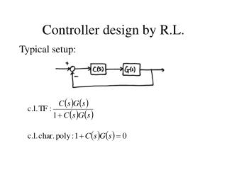
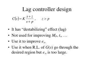
Controller Design • Five step controller design process
outputs FSM inputs x FSM b FSM outputs Combinational logic n1 n0 s1 s0 State register clk Controller Design: Laser Timer Example • Step 1: Capture the FSM • Already done • Step 2: Create architecture • 2-bit state register (for 4 states) • Input b, output x • Next state signals n1, n0 • Step 3: Encode the states • Any encoding with each state unique will work Inputs: b; Outputs: x x=0 00 b ’ O ff b x=1 x=1 x=1 01 On1 10 On2 11 On3
Controller Design: Laser Timer Example (cont) • Step 4: Create state table Inputs: b; Outputs: x x=0 00 b ’ O ff b x=1 x=1 x=1 01 On1 10 On2 11 On3
x = s1 + s0(note from the table that x=1 if s1 = 1 or s0 = 1) n1 = s1’s0b’ + s1’s0b + s1s0’b’ + s1s0’b n1 = s1’s0 + s1s0’ n0 = s1’s0’b + s1s0’b’ + s1s0’b n0 = s1’s0’b + s1s0’ Controller Design: Laser Timer Example (cont) • Step 5: Implement combinational logic
FSM outputs Combinational Logic b x FSM inputs n1 n0 s0 s1 State register clk Controller Design: Laser Timer Example (cont) • Step 5: Implement combinational logic (cont) x = s1 + s0 n1 = s1’s0 + s1s0’ n0 = s1’s0’b + s1s0’
x=0 x=0 x=0 00 00 00 b ’ b ’ b ’ O ff O ff b b x=1 x=1 x=1 x=1 x=1 x=1 10 10 11 01 11 01 On1 On2 On3 On1 On2 On3 b b x x 0 0 0 0 1 1 0 0 1 0 0 1 0 0 1 n1 n1 0 0 1 0 0 0 0 1 0 n0 n0 0 1 0 0 0 0 s1 s0 s1 s0 clk clk 0 0 0 0 0 1 0 0 0 1 1 0 st a t e=00 st a t e=00 st a t e=01 Understanding the Controller’s Behavior O ff b x=1 x=1 x=1 01 10 11 On1 On2 On3 b x n1 n0 s0 s1 clk clk I nputs: b O utputs: x
Controller Example: Button Press Synchronizer • Want simple sequential circuit that converts button press to single cycle duration, regardless of length of time that button actually pressed • We assumed such an ideal button press signal in earlier example, like the button in the laser timer controller Button press synchronizer controller bi bo
Step 2: Create architecture bi bo FSM outputs FSM inputs FSM inputs: bi; FSM outputs: bo Combinational logic bi ’ n1 bi b i ’ n0 bi ’ C A B s1 s0 bi bi n1 = s1’s0bi + s1s0bi n0 = s1’s0’bi bo = s1’s0bi’ + s1’s0bi = s1s0 State register bo=0 bo=1 bo=0 clk Step 1: FSM Combinational logic outputs bo bi n1 FSM inputs: bi; FSM outputs: bo bi ’ bi n0 bi ’ bi ’ 10 00 01 bi bi bo=0 bo=1 bo=0 s1 s0 Step 3: Encode states State register clk Step 4: State table Step 5: Create combinational circuit Controller Example: Button Press Synchronizer (cont) FSM Step 5: Create combinational circuit
w Inputs: none; Outputs: w,x,y,z Inputs: none; Outputs: w,x,y,z x y wxyz=0001 wxyz=1000 wxyz=0001 wxyz=1000 Combinational logic z A D A D n1 00 11 n0 s1 s0 01 10 State register B C B C clk wxyz=0011 wxyz=1100 wxyz=0011 wxyz=1100 Step 2: Create architecture Step 1: Create FSM Step 3: Encode states w FSM outputs x y z n0 n1 s1 s0 State register clk Step 4: Create state table Controller Example: Sequence Generator • Want generate sequence 0001, 0011, 1100, 1000, (repeat) • Each value for one clock cycle • Common, e.g., to create pattern in 4 lights, or control magnets of a “stepper motor” w = s1 x = s1s0’ y = s1’s0 z = s1’ n1 = s1 xor s0 n0 = s0’ Step 5: Create combinational circuit
I nputs: a ; O utputs: r Inputs: a; Outputs: r 000 Wait a ’ r=0 r=0 a ’ a a Step 1 K1 K2 K3 K4 100 001 010 011 r=1 r=1 r=0 r=1 r=1 r=1 r=0 r=1 outputs a r Combinational logic FSM n2 inputs Step 2 n1 n0 s2 s1 s0 State register clk Step 3 Step 4 Controller Example: Secure Car Key • (from earlier example) FSM We’ll omit Step 5
states FSM outputs y x z FSM inputs states with outputs n1 n0 s1 s0 State register clk Pick any state names you want states with outputs and transitions Example: Seq. Circuit to FSM (Reverse Engineering) y=s1’ z = s1s0’ n1=(s1 xor s0)x n0=(s1’*s0’)x What does this circuit do? Work backwards