Model-Based Controller Design
Model-Based Controller Design. Introduction Direct synthesis method Internal model control (IMC) IMC derived PID tuning rules Simulink example. Model-Based Control. PID controller tuning Restrict controller to PID form Seek “best” tuning parameters

Model-Based Controller Design
E N D
Presentation Transcript
Model-Based Controller Design • Introduction • Direct synthesis method • Internal model control (IMC) • IMC derived PID tuning rules • Simulink example
Model-Based Control • PID controller tuning • Restrict controller to PID form • Seek “best” tuning parameters • Can be perform with FOPTD model if available • Model-based controller design • Controller is not restricted to PID form • Requires a process model that is used to determine the controller form as well as the tuning parameters • Not restricted to FOPTD models • Makes full use of available model • Generates PID controllers for many model types
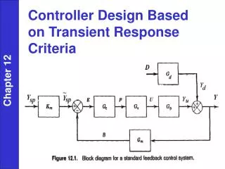
Direct Synthesis Method • Closed-loop transfer function for setpoint changes • Simplification of CLTF
Control Objective • Rearrange CLTF • Desired setpoint response • Gd is the desired CLTF • The controller Gc depends explicitly on the inverse of the process model G • The equation for Gc is known as the control law
Desired Closed-Loop Transfer Function • The desired CLTF Gd is specified such that: • The resulting Gc has a single tuning parameter with an easily understood effect on closed-loop stability and performance • Gc is implementable – does not require prediction and has the appropriate properness • Properness • If n >= m, the controller is proper no derivative control • If n = m-1, the controller is improper derivative control • If n = m-2, the controller is improper requires second derivative of measured output (not implementable) • Seek controllers that are proper or improper with n = m-1
Selecting the Desired CLTF • Common choice • tc > 0 is the desired closed-loop time constant • Gd is stable for all tc > 0 • Gd has a steady-state gain of unity ensuring offset-free performance due to integral action in Gc • Closed-loop speed of response is determined by tc; typical choice is tc = 0.5t • Other choices of Gd may be required to ensure that Gc is implementable
Simple Examples • First-order system • This is a PI controller! • Second-order system • This is a PID controller!
Systems with Time Delays • Model representation: • Desired CLTF • FOPTD model
Non-Minimum Phase Systems • Process Model • Zeros: N(s) = 0 • Systems with right-half plane zeros can exhibit inverse response • Such systems are said to be non-minimum phase • Direct synthesis controller • Zeros of model become poles of controller • Controller is unstable if model is non-minimum phase
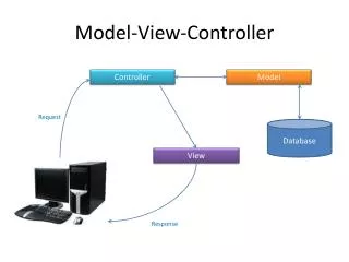
Internal Model Control • Applicable to both minimum-phase and non-minimum phase systems • Do not invert non-invertible elements: time delays and right-half plane zeros • IMC approach • Factor model into invertible and non-invertible parts • Design IMC controller using the IMC control structure • Convert IMC controller into standard feedback controller • Implement standard feedback controller as usual
IMC Design • Factor the process model • contains any time delays and right-half plane zeros, has unity gain and is an all-pass element • Construct the IMC controller • f is the IMC filter, tc is the desired closed-loop time constant and r is chosen to G*c proper • Resulting closed-loop relation
First-Order System • This is a PI controller • Same result as direct synthesis method • Two methods always yield same result when G+ = 1
Non-Minimum Phase Examples • Right-half plane zero • Time delay