Download
1 / 20
250 likes | 589 Views
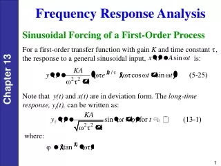
12. Frequency Response Analysis (II). Yonsei University Mechanical Engineering Prof. Hyun Seok YANG. [Relationships between O.L. Bode Plot & C.L. Bode Plot ]. +. w.o.l.g, assume. Define “open-loop transfer function” : Define “closed-loop transfer function” :.

E N D
12. Frequency Response Analysis (II) Yonsei University Mechanical Engineering Prof. Hyun Seok YANG
[Relationships between O.L. Bode Plot & C.L. Bode Plot] + w.o.l.g, assume Define “open-loop transfer function” : Define “closed-loop transfer function” :
[Q] If you know the Bode mag. plot of O.L.T.F, can you deducibly find the Bode mag. Plot of C.L.T.F? => YES!! Since (Gain Crossover Freq.) When When Bandwidth When -3dB -6dB
* In the region where mag. ratio is larger than 0 dB in O.L.T.F Bode mag. plot, the mag. ratio is on 0 dB line in C.L.T.F Bode mag. plot. * In the region where mag ratio is much smaller than 0 dB in O.L.T.F Bode mag. plot, the mag ratio of C.L.T.F Bode mag. plot is almost the same as that of O.L.T.F Bode mag. plot. * The mag ratio of C.L.T.F. at the Gain Crossover Frequency is -6 dB. [Bandwidth] The freq. range where the ratio of the output to input is between 0dB(100%)~-3dB(70%) Namely, when the input frequency is in the range of Bandwidth, the output magnitude follows at least 70 % of the input magnitude. [Control System Performance in Frequency Domain] (a) Command Following (Tracking) (b) Disturbance Rejection (c) Noise Attenuation (Reduction)
Bandwidth Bandwidth Bandwidth [a] Command Following Performance [as gain increases] [Example] + • As Gain K is increased, • - C.L. Time Constant becomes smaller, • and the response speed becomes faster. • Bandwidth becomes wider, • and the output magnitude follows the input • magnitude for the wider range of the input • frequency.
+ + + [b] Disturbance Rejection Performance [as gain increases] : Sensitivity T.F. When When When Disturbance Freq. Range As Gain K is increased, the effect of the disturbance reject becomes better. -6dB
+ [c] Noise Reduction Performance + [as gain increases] + As Gain K is increased, the effect of noise rejection becomes worse. • For command following & dist. rej., • gain should be large. • For noise reduction Gain should be small. • - Those two are conflict to each other. Noise Freq. Range [Note] (Bode’s Integral Theorem) C + S = 1
+ + [Example] Noise freq. range Design Spec. : Bandwidth = 50 rad/sec => approximately gain crossover = 50 rad/sec 50rad/sec Low pass filter • But, if noise freq is around at 100~300rad/sec ? • Add a “Low Pass Filter”. (e.g. ) • The noise reduction effect is increased. + + Low pass filter
[Relative Stability: Gain Margin & Phase Margin] [O.L.T.F.] Phase Crossover Freq. G.M.(-) G.M.(+) Gain Crossover Freq. • For minimum phase system, • Closed-loop system is stable • if and only if • G.M. > 0 dB • & P.M. > 0 deg • Roughly, damping ratio • of dominant 2nd order pole • = 0.01 x P.M. • i.e. for better damping, P.M. P.M.(+) -180o P.M.(-) [Phase Crossover Freq.]
[Lead & Lag Compensator] [Lead Compensator] -Basically, to increase bandwith & response speed. to decrease overshoot (better damping). [Lag Compensator] -Basically, to increase low freq. gain (better disturbance rejection)
[Compensator Design Concept Examples] Design Problem 1 Design Spec. : %OS = 9.5%
K=3.6 K=3.6x 162.2 =583.9 P.M. = 60o 14.8
[Example] Frequency response plots of a lag compensator,
Low freq. gain increased, while crossover kept the same Visualizing lag compensation
Design Problem 2 Design Lag compensator to yield a tenfold improvement in steady-state error while keeping the %OS = 9.5% Low freq. gain boosted up K=5839 10 dec 0.062 0.98 -110.8o P.M. kept the same 9.8
[Example] Frequency response of a lead compensator,
Visualizing lead compensation P.M, increased while low freq gain kept the same
Design Problem 3 Design Lead compensator to yield a 20% overshoot and Kv=40, with peak time= 0.1sec. -3.77 dB K=1440 39