Frequency Response
Chapter 14 EGR 272 – Circuit Theory II. 1. Read : Ch. 14, Sect. 1-5 in Electric Circuits, 9 th Edition by Nilsson. Frequency Response


Frequency Response
E N D
Presentation Transcript
Chapter 14 EGR 272 – Circuit Theory II 1 Read: Ch. 14, Sect. 1-5 in Electric Circuits, 9thEdition by Nilsson Frequency Response This is an extremely important topic in EE. Up until this point we have analyzed circuits without considering the effect on the answer over a wide range of frequencies. Many circuits have frequency limitations that are very important. Example: Discuss the frequency limitations on the following items. 1) An audio amplifier 2) An op amp circuit
Chapter 14 EGR 272 – Circuit Theory II 2 Example: Discuss the frequency limitations on the following items (continued) 3) A voltmeter (% error vs frequency) 4) The tuner on a radio (band-pass filter)
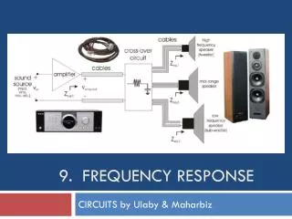
Chapter 14 EGR 272 – Circuit Theory II 3 Filters A filter is a circuit designed to have a particular frequency response, perhaps to alter the frequency characteristics of some signal. It is often used to filter out, or block, frequencies in certain ranges, much like a mechanical filter might be used to filter out sediment in a water line. • Basic Filter Types • Low-pass filter (LPF) - passes frequencies below some cutoff frequency, wC • High-pass filter (HPF) - passes frequencies above some cutoff frequency, wC • Band-pass filter (BPF) - passes frequencies between two cutoff frequency, wC1 and wC2 • Band-stop filter (BSF) or band-reject filter (BRF) - blocks frequencies between two cutoff frequency, wC1 and wC2
Chapter 14 EGR 272 – Circuit Theory II 4 Ideal filters An ideal filter will completely block signals with certain frequencies and pass (with no attenuation) other frequencies. (To attenuate a signal means to decrease the signal strength. Attenuation is the opposite of amplification.) LM LM Ideal LPF Ideal HPF w w wC wC LM LM Ideal BPF Ideal BSF w w wC1 wC2 wC1 wC2
Chapter 14 EGR 272 – Circuit Theory II 5 Filter order Unfortunately, we can’t build ideal filters. However, the higher the order of a filter, the more closely it will approximate an ideal filter. The order of a filter is equal to the degree of the denominator of H(s). (Of course, H(s) must also have the correct form.) LM Ideal LPF 4th-order LPF 3rd-order LPF 2nd-order LPF 1st-order LPF w wC
Chapter 14 EGR 272 – Circuit Theory II 6 Defining frequency response Recall that a transfer function H(s) is defined as: Where Y(s) = some specified output and X(s) = some specified input In general, s = + jw. For frequency applications we use s = jw (so = 0). So now we define: Since H(jw) can be thought of as a complex number that is a function of frequency, it can be placed into polar form as follows:
Chapter 14 EGR 272 – Circuit Theory II 7 Example: Find H(jw) for H(s) below. Also write H(jw) in polar form. When we use the term "frequency response", we are generally referring to information that is conveyed using the following graphs:
Chapter 14 EGR 272 – Circuit Theory II 8 Example: A) Find H(s) = Vo(s)/Vi(s) B) Find H(jw)
Chapter 14 EGR 272 – Circuit Theory II 9 Example: (continued) C) Sketch the magnitude response, |H(jw)| versus w D) Sketch the phase response, (w) versus w E) The circuit represents what type of filter?
Chapter 14 EGR 272 – Circuit Theory II 10 Example: A) Find H(s) = V(s)/I(s) B) Find H(jw)
Chapter 14 EGR 272 – Circuit Theory II 11 Example: (continued) C) Sketch the magnitude response, |H(jw)| versus w D) Sketch the phase response, (w) versus w E) The circuit represents what type of filter?
Chapter 14 EGR 272 – Circuit Theory II 12 Example: A) Find H(s) = Vo(s)/Vi(s) B) Find H(jw)
Chapter 14 EGR 272 – Circuit Theory II 13 Example: (continued) C) Sketch the magnitude response, |H(jw)| versus w D) Sketch the phase response, (w) versus w E) The circuit represents what type of filter?
Chapter 14 EGR 272 – Circuit Theory II 14 General 2nd Order Transfer Function For 2nd order circuits, the denominator of any transfer function will take on the following form: s2 + 2s + wo2 Various types of 2nd order filters can be formed using a second order circuit, including:
Chapter 14 EGR 272 – Circuit Theory II 15 Series RLC Circuit (2nd Order Circuit) Draw a series RLC circuit and find transfer functions for LPF, BPF, and HPF. Note that the denominator is the same in each case (s2 + 2s + wo2). Also show that:
Chapter 14 EGR 272 – Circuit Theory II 16 Parallel RLC Circuit (2nd Order Circuit) Draw a parallel RLC circuit and find transfer functions for LPF, BPF, and HPF. Note that the denominator is the same in each case (s2 + 2s + wo2). Also show that:
Chapter 14 EGR 272 – Circuit Theory II 17 2nd Order Bandpass Filter A 2nd order BPF will now be examined in more detail. The transfer function, H(s), will have the following form: • Magnitude response • Show a general sketch of the magnitude response for H(s) above • Define wo , wc1 , wc2 , Hmax , BW, and Q • Sketch the magnitude response for various values of Q (in general)
Chapter 14 EGR 272 – Circuit Theory II 18 Determining Hmax Find H(jw) and then H(jw). Show that
Chapter 14 EGR 272 – Circuit Theory II 19 Determining wc1 and wc2 : Show that leads to
Chapter 14 EGR 272 – Circuit Theory II 20 Determining wo, BW, and Q: Show that wo is the geometric mean of the cutoff frequencies, not the arithmetic mean. Also find BW and Q. Specifically, show that: Damping ratio is simply defined here. Its significance will be seen later in this course and in other courses (such as Control Theory). Circuits with similar values of z have similar types of responses.
Chapter 14 EGR 272 – Circuit Theory II 21 Example: A parallel RLC circuit has L = 100 mH, and C = 0.1 uF 1) Find wo , , Hmax , wc1 , wc2 , Hmax , BW, Q, and z 2) Show that wo is the geometric mean of the wc1 and wc2 , not the arithmetic mean. A) Use R = 1 kW
Chapter 14 EGR 272 – Circuit Theory II 22 Example: A parallel RLC circuit has L = 100 mH, and C = 0.1 uF 1) Find wo , , Hmax , wc1 , wc2 , Hmax , BW, Q, and z 2) Show that wo is the geometric mean of the wc1 and wc2 , not the arithmetic mean. B) Use R = 20 kW
Chapter 14 EGR 272 – Circuit Theory II 23 |H(jw)| 5k 6k 7k 8k 9k 10k 20k w (log scale) Example: Plot the magnitude response, |H(jw)|, for parts A and B in the last example. (Note that a curve with a geometric mean will appear symmetrical on a log scale and a curve with an arithmetic mean will appear symmetrical on a linear scale.)