Download
1 / 34
340 likes | 429 Views
Learn about the basics of X-rays, CT hardware components, measurement techniques, reconstruction methods, and imaging local tissue properties through grayscale or color mapping. Explore applications like Whole Body CT, Peripheral CT, Microtomography, and 3D Microtomography. Understand CT measurement principles and artifacts, including Beam Hardening and Detector systems. Discover reconstruction techniques such as Iterative and Convolution-Backprojection, and common image artifacts in CT scans. Dive into resources required for high-resolution CT imaging and techniques to minimize artifacts.

E N D
Computed TomographySCANCO User Meeting 2005 Dr. Bruno Koller SCANCO Medical AG www.scanco.ch
Overview • X-Ray Basics • CT Hardware Components • Measurement • Reconstruction • Artefacts
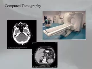
Introduction • 3D distribution of tissue-properties • Density (absorption of X-rays, speed of sound…) • Chemical composition • Temperature • ... • Imaging of these local tissue properties using grayscale or color mapping
Whole Body CT • Good S/N • Good contrast bone/soft tissue • Slice thickness 2-5 mm 2 cm
Peripheral CT • Good Contrast Bone/Soft tissue • Voxelsize 100 mm • Limited FOV (130 mm) 1 cm
Microtomography • Excellent contrast bone/soft tissue • Slice thickness and in plane resolution <10 mm • More noise in images 1 mm
CT-Basics • Based on measurement of attenuation of X-rays (Beer-Lambert): • Measurement of a projection value (Sample): Source Detector m Io I d
Measurement of one projection Io I t t
Projection Value Measurement I I I0 m X-rays Source Object Detector
Source • X-Ray Tubes (most common) • Continuous, steady output (high flux) • Small focal spot (< 10 mm) • Variable energy and intensity • Polychromatic beam I E
Attenuation coefficient m [1/cm] • Attenuation coefficient changes with material: • Attenuation coefficient changes with energy: m bonemusclefat E
I I E E Beam Hardening • Soft X-rays are attenuated more than hard X-rays • Depending on object, spectrum changes m(E) d
Detectors • Usually detect visible light only • Counting Systems (Photomultipliers) • Integrating Systems (CCD, Diode Arrays, CMOS-Detectors) • They all need Scintillators • Convert X-rays into light • NaI, CsI, CdTe ... • The thicker, the more efficient, but the thiner, the better the spatial resolution (tradeoff between high output or high res) • Fiber optics (straight or tapered) in between to protect from remaining X-rays
CT-Measurement • For a CT measurement one needs an certain number of single projection measurements at different angles (theoretically, an unlimited number is required) • In realized Tomography-Systems one usually finds a geometrically ordered detector configuration
1st generation scanner • Single Detector System • Translation-Rotation • 5 min. per slice
2nd generation scanner • multichannel-Systems (4, 6, 8, 16) • Translation-Rotation • 20 sec. per slice
3rd generation scanner • Fan-Beam-Geometry • multichannel-system (500+ detectors), angle > 180o • Rotation of tube and detektorsystem • no translation • 1 – 10 sec. per slice
Parallel Beam (Synchrotron) • Parallelbeam • Rotation of object only • No collimators required • 2D-Detector arrays A. Kohlbrenner, ETH Zürich
Cone Beam • Tube with focal spot • Linear, 2-D Detector (e.g. 1024 x 1024 Elements, CCD) • Single rotation • Artefacts due to improper scanning scheme (would require to different movements) A. Kohlbrenner, ETH Zürich
Spiral scanning • Continuous movement of patient during rotation • Volumetric measurement • Slicewise reconstruction with variable slice thickness by interpolation • As scanner can continuously rotate, one can achieve much faster scan speeds • Latest models (clinical scanners) with parallel detector rings (Multirow, currently up to 64) • 40 slices per second (150 rpm) • No need in current MicroCT systems as the rotation speed is low
Reconstruction • Iterative reconstruction • ART (Arithmetic Reconstruction Technique) • Assume image (base image) • Calculate projections of this base image • Modify image after comparing calculated projections with measured Projections • Strategy...
Reconstruction • Direct method: The measured projections are backprojected under the same angle as the measurement was taken. All projections are summed up
Artefacts • Beam Hardening • Attenuation coefficients depend on energy • soft X-rays are much more absorbed than harder X-rays • Distribution changes when beams penetrate object • Segmentation problems
Artefacts • Object outside of FOV • Inconsistent set of projection data (only partially within the beam at some angles, completely in the beam at other angles) • Local Reconstruction: only for geometry
Artefacts • Motion • Object moves during scan • May be eliminated by external gating (respiratory, heart beat) • Total absorption of X-Rays e.g. Caused by metallic implants (division by 0 in reconstruction) • Other Artefacts • Wrong geometry (fan-beam-angle) • Centers artefact • Mechanical alignment • Insufficient no. of projections (sampling) • ...
Resources • Volume of 1024 x 1024 x 1200 requires 2.4 GB (short integer) • Doubling the resolution requiers 8x more time to calculate • Doubling the resolution requiers 8x more disk space