Aztec PC Scope Preliminary Design Review Fall 2006
270 likes | 414 Views
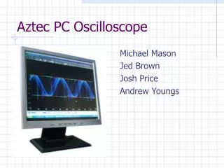
Aztec PC Scope Preliminary Design Review Fall 2006. Michael Mason Jed Brown Andrew Youngs Josh Price . Aztec PC Oscilloscope. Project Description. An Oscilloscope that will interface with a PC 2 Initial Modes

Aztec PC Scope Preliminary Design Review Fall 2006
E N D
Presentation Transcript
Aztec PC Scope Preliminary Design Review Fall 2006 Michael Mason Jed Brown Andrew Youngs Josh Price
Project Description An Oscilloscope that will interface with a PC • 2 Initial Modes • Trigger Based - Once the programmable conditions have been met the scope will pass information to the ram. • Free Flow – As soon as enabled it will pass the data to the ram and potentially to the PC.
Purpose • To provide a cost effective oscilloscope • Make the scope affordable to a wider range of customers. • Facilitate use of a PC in lab testing • Allow students and engineers to use the PC to capture data for storage or use in reports. • Design for possible extensions in the future • The concept is easily expandable.
Features • User Defined Sample Rate. • Free flow Mode • Definable trigger Mode • Data upload to PC • Toggle Impedance (50 Ohm/100 Ohm) • Graphical User Interface
Basic Flow • Scope Signal Conditioner Analog/Digital converter FPGA Memory MC USB
Block Diagram Scope USBController M C SD R A M S C MUX A/D • Spartan-3EHW-SPAR3E-SK-US eeprom
Scope & Signal Converter • One Channel • Slow speed with possibilities to upgrade • Signal converter • Needed to scale the signal to < 5.0 volts for the A/D converter. • Multiplexor is for future additions to the scope • Additional channels would require additional A/D converters. Design should make adding channels simple.
Input Signal Issues • Noise • DC Offset • Signal Amplitude
Signal Conditioning Solutions • Filtering • AC/DC Coupling • Signal Amplification
Filtering • Bessel Low Pass Filter • Notch Filter
AC/DC Coupling • DC Coupling • AC Coupling
Signal Amplification • Pre-Amplification • Variable • High Bandwidth • Flat Frequency Response
Analog to Digital Converter • Single serial input, 8-bit parallel output • Maximum Conversion Rate of 40 Megasamples/second
Microcontroller • Initially use Siemens 8051 • 16-bit addressable, 8-bit data, 64kB accessible external RAM • Basic control unit for enables, external peripherals (LCD, SRAM, EEPROM, ADC) • Will interface with the computer for sending data and receiving user commands (interface with RS232 and USB). • Possible upgrade if time permits
Microcontroller Block Diagram EEPROM SRAM 8051 LCD PC/GUI Serial Interface • Spartan-3E
AC/DC Converter • Utility connected (120 VAC 60 Hz) to board power (+5 VDC) • DC/DC on board power conversion can be accomplished through level shifters, voltage regulators.
RS232 Level Converter • A standard serial interfacing for PC, RS232C, requires negative logic, i.e., logic '1' is -3V to -12V and logic '0' is +3V to +12V • 2-channel RS232C port and requires external 10uF capacitors
USB Controller • First Serial, then USB • DLP-2232M-G - Dual USB UART/FIFO • UART Interface supports 7/8 bit data, 1/2 stop bits, and Odd/Even/Mark/Space/No Parity • Transfer Data Rate 300 to 1 Mega Baud (RS232)
Spartan-3E FPGA Board • Xilinx Devices: • Spartan-3E (XC3S500E-4FG320C) • CoolRunner™-II (XC2C64A-5VQ44C) • Platform Flash (XCF04S-VO20C) • Clocks: 50 MHz crystal clock oscillator • Memory • 128 Mbit Parallel Flash • 16 Mbit SPI Flash • 64 MByte DDR SDRAM
Spartan-3E FPGA Board cont. • Connectors and Interfaces • Ethernet • JTAG USB download • Two 9-pin RS-232 Serial Port, • PS/2- style mouse/keyboard port • rotary encoder with push button • Four Slide Switches • Eight Individual LED Outputs • Four Momentary-Contact Push Buttons • 100-Pin hirose Expansion Connection Ports • Three 6-pin expansion connectors • Display: 16 character - 2 Line LCD
Risks and Contingency Plan • Use the serial ports on the FPGA board, or microcontroller instead of the USB interface. • Decrease capabilities of the graphing software. • Use FPGA board interfaces to program triggers and sampling rate instead of USB interface.
Endless Possibilities • Wireless probe to gather the data. • Advanced User Interface with measurement and display controls. • Multiple channels on the scope.
Labor & Responsibilities • Mike – Software, USB (Windows Drivers) • Jed – Software, FPGA (verilog) • Andrew – Signal Conditioning, A/D • Josh - Power, Microcontroller, RS232 • ALL – PCB