Download

1 / 31
320 likes | 488 Views
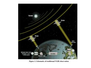
Chapter 20 Fundamentals of Machining/Orthogonal Machining Part 2 (Review) EIN 3390 Manufacturing Processes Summer A, 2012. FIGURE 20-17 Schematic representation of the material flow, that is, the chip-forming shear process. f defines the onset of shear or lower boundary.

E N D
Chapter 20Fundamentals of Machining/Orthogonal MachiningPart 2(Review)EIN 3390 Manufacturing ProcessesSummer A, 2012
FIGURE 20-17 Schematic representation of the material flow, that is, the chip-forming shear process. f defines the onset of shear or lower boundary. y defines the direction of slip due to dislocation movement. tc
Assume that 1) the shear process takes place on a single narrow plane as A-B in figure 20- 19. 2) tools cutting edge is perfectly sharp and no contact is being made between the flank of the tool and the new surface. Chip thickness ratio based on trigonometry: rc = t / tc = (AB sin f)/[ABcos(f - a)], or tan f = (rccosa)/(1 - rcsina) Where AB – length of the shear plane from the tool tip to the free surface. 20.5 Merchant’s Model
For consistency of volume, rc = t / tc = (sin f)/[cos(f - a)] = Vc./V, and Vs / V = (cosa)/[cos(f - a)] Where V – velocity for workpiecepasing tool, Vc – chip moving velocity, Vs – shearing velocity, f – onset of shear angle, a - rake angle . 20.5 Merchant’s Model
FIGURE 20-19 Velocity diagram associated with Merchant’s orthogonal machining model.
Assume that the result force R acting on the back of the chip is equal and opposite to the resultant force R’ acting on the shear plane. R is composed of friction force F and normal force N acting on tool-chip interface contact area. R’ is composed of a shear force Fsand normal force Fnacting on the shear plane area As. R is also composed of cutting force Fcand tangential (normal) force Ft acting on tool-chip interface contact area. Ft = R sin (b - a) 20.6 Mechanics of Machining (statics)
FIGURE 20-20 Free-body diagram of orthogonal chip formation process, showing equilibrium condition between resultant forces R and R.
a a FIGURE 20-21 Merchant’s circular force diagram used to derive equations for Fs , Fr , Ft , and N as functions of Fc, Fr , f, a, and b.
Friction force F and normal force N are: F = Fcsina + Ftcosa, N = Fccosa - Ftsina, and b = tan-1m = tan-1 (F/N), Where m - friction coefficient, and b – the angle between normal force N and resultant R. If a = 0, then F = Ft , and N = Fc . in this case, the friction force and its normal can be directly measured by dynamometer. R = SQRT (Fc2 + Ft2 ), Fs = Fccosf - Ftsinf, and Fn = Fcsinf + Ftcosf, Where Fs is used to compute the shear stress on the shear plane 20.6 Mechanics of Machining (statics)
Shear stress: ts= Fs/As, Where As - area of the shear plane, As = (t w)/sinf Where t – uncut ship thickness and w – width of workpiece. ts= (Fcsinfcosf - Ft sin2f )/(tw) psi In metal cutting shear stress is a material constant. For a given metal, shear stress is not sensitive to variations in cutting parameters, tool material, or cutting environment. Once this value is known for a metal, it can be used in basic engineering calculations for machining statics (forces and deflection) and dynamics (vibration and chatter). Fig. 20-22 shows some typical values for flow stress for a variety of metals, plotted against hardness. 20.6 Mechanics of Machining (statics)
FIGURE 20-22 Shear stress tsvariation with the Brinell hardness number for a group of steels and aerospace alloys. Data of some selected fcc metals are also included. (Adapted with permission from S. Ramalingham and K. J. Trigger, Advances in Machine Tool Design and Research, 1971, Pergamon Press.)
Use Merchant’s chip formation model, a new “stack-of-cards” model as shown in fig. 20-23 is developed. From the model, strain is: g= cosa/[sin(f + y) cos(f + y -a)] where f - the angle of the onset of the shear plane, and y - the shear front angle. The special shear energy (shear energy/volume) equals shear stress x shear strain: Us = t .g 20.7 Shear Strain g & Shear Front Angle f
g= AB/CD = AD/CD + DB/CD = cot(f + y) + tan(f + y -a) = cosa/[sin(f + y) cos(f + y -a)] 20.7 Shear Strain g & Shear Front Angle f
Use minimum energy principle, where will y take on value (shear direction) to reduce shear energy to a minimum: • d(Us)/dy = 0, • Solving the equation above, • cos(2f + 2y -a) = 0 • 2f + 2y - a = 900 • y = 450 - f + a/2, and • g= 2cosa/(1 + sina), • It shows the shear strain is dependent only on the rake angle a. 20.7 Shear Strain g & Shear Front Angle f
FIGURE 20-23 The Black–Huang “stack-of-cards” model for calculating shear strain in metal cutting is based on Merchant’s bubble model for chip formation, shown on the left.
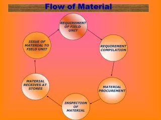
Machining is a dynamic process of large strain and high strain rate. The process is a closed loop interactive processes as shown on fig. 20-24. 20.8 Mechanics of Machining (Dynamics)
Free vibration is the response to any initial condition or sudden change. The amplitude of the vibration decreases with time and occurs at the natural frequency of the system. Forced vibration is the response to a periodic (repeating with time) input. The response and input occur at the same frequency. The amplitude of the vibration remains constant for set input condition. 20.8 Mechanics of Machining (Dynamics)
Self-excited vibration is the periodic response of the system to a constant input. The vibration may grow in amplitude and occurs near natural frequency of the system regardless of the input. Chatter due to the regeneration of waviness in the machining surface is the most common metal cutting example. 20.8 Mechanics of Machining (Dynamics)
Factors affecting on the stability of machining • Cutting stiffness of workpiece material (machinability), Ks • Cutting –process parameters (speed, feed, DOC, total width of chip) • Cutter geometry (rake and clearance angles, insert size and shape) • Dynamic characteristics of the machining process (tooling, machining tool, fixture, and workpiece) 20.8 Mechanics of Machining (Dynamics)
Chip formation and regenerative Chatter • In machining, chip is formed due to shearing of workpiece material over chip area (A = t x w), which results in a cutting force. • Magnitude of the resulting cutting force is predominantly determined by the material cutting stiffness Ks and the chip area such that Fc = Ks t w. • The direction of the cutting force Fc in influenced mainly by the geometries of rack and clearance angles and edge prep. 20.8 Mechanics of Machining (Dynamics)
Factors Influencing Chatter: • Cutting stiffness Ks(Machinability): The larger stiffness, the larger cutting force, and the less machining stability. • Speed: At slow speed (relative to the vibration frequency), as speed increases, chatter gets more significant. • Feed: does not greatly influence stability, but control amplitude of vibration. • DOC: The primary cause and control of chatter. • Total width of chip: DOC times number of cutting edges in cutting. Increase number of engaged cutting edges will result in chatter. 20.8 Mechanics of Machining (Dynamics)
Factors Influencing Chatter: • Back rake angle: increasing it will reduce magnitude of cutting force, and increase process stability. • Clearance angle: reducing it will increase frictional contact between tool and workpiece, and may produce process damping. • Size (nose radius), shape (diamond, triangular, square, round) and lead angle of insert. 20.8 Mechanics of Machining (Dynamics)
Energy dissipated in cutting is converted to heat, elevating temperature of chip, workpiece, and tool. • As speed increases, a greater percentage of the heat ends up in the chip. • Three sources of heat: • Shear front. • Tool-chip interface contact region. • Flank of the tool. Effects of Temperature
FIGURE 20-31 Distribution of heat generated in machining to the chip, tool, and workpiece. Heat going to the environment is not shown. Figure based on the work of A. O. Schmidt.
FIGURE 20-31 Distribution of heat generated in machining to the chip, tool, and workpiece. Heat going to the environment is not shown. Figure based on the work of A. O. Schmidt.
FIGURE 20-32 There are three main sources of heat in metal cutting. (1) Primary shear zone. (2) Secondary shear zone tool–chip (T–C) interface. (3) Tool flank. The peak temperature occurs at the center of the interface, in the shaded region.
FIGURE 20-32 There are three main sources of heat in metal cutting. (1) Primary shear zone. (2) Secondary shear zone tool–chip (T–C) interface. (3) Tool flank. The peak temperature occurs at the center of the interface, in the shaded region.
Excessive temperature affects • strength, hardness and wear resistance of cutting tool. • dimensional stability of the part being machined. • machined surface properties due to thermal damage • the machine tool, if too excessive. Effects of Temperature
FIGURE 20-33 The typical relationship of temperature at the tool–chip interface to cutting speed shows a rapid increase. Correspondingly, the tool wears at the interface rapidly with increased temperature, often created by increased speed.
High-strength materials produce larger cutting forcesthan materials of lower strength, causing greater tool and work deflection; increased friction, heat generation, operation temperature. Work hardness prior to machining controls the onset of shear. Highly ductile materials generate extensive plastic deformation of the chip, which increases heat, temperature, and longer, continuous chips. A variation of the continuous chip, often encountered in machining ductile materials, is associated a bill-up-edge (BLE) formation on the cutting tool. BLEs are not stable and will break off periodically. BUE formation can be minimized by reducing depth of cut, altering cutting speed, using positive rake tools, applying a coolant, or changing cutting-tool materials. Summary
Review Questions: 15, and 24 (pages 557 – 558) Problem 7. After your calculation, please compare your HPs and ts with HPs values in table 20-3, and ts values in Figure 20-22. HW for Chapter 20