Download
1 / 27
270 likes | 421 Views
This document explores the application of MSG satellite images in the analysis of wave and upper wave structures, comparing them with MTP channels. Key focus areas include the distinct advantages of MSG over MTP, such as sharper contours, improved spatial resolution, and additional channel information. The study highlights the identification of microphysical properties of clouds and the significance of varying atmospheric parameters in enhancing contrast between different cloud types. The findings are aimed at improving weather forecasting accuracy using advanced satellite imagery techniques.

E N D
Conceptual Models (CMs):Wave - Upper wave How to use MSG satellite images similarities to and improvements over MTP Contact person: Veronika Zwatz-Meise zwatz-meise@zamg.ac.at Version 1.0. 13 July 2004
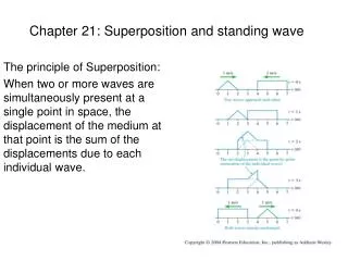
CM:Wave - Upper wave • MTP channels in comparison with the corresponding MSG channels • CM Wave: IR image + relevant NWP parameters • MSG additional channels + Channel combinations • WV and WV difference images
MTP: ir As the image time between MTP and MSG differs, a shift between the cloud systems can be noticed in the two images
MSG: ch09 Sharper contours through improved space resolution
MSG: ch01 Looks relatively similar; but: somewhat coarser space resolution
MSG:129 Sharper contours and more detailed grey-shades through improved space resolution in IRand additional information from 2 different VIS channels
CM:Wave - Upper wave • MTP channels in comparison with the corresponding MSG channels • CM Wave: IR image + relevant NWP parameters • MSG additional channels + Channel combinations • WV and WV difference images
H1000 Upper wave: No or only very weak surface minimum
H500 Wave and upper wave: Upper level trough at rear side of front
Equ. Thickness + TFP Thickness gradient and TFP; transition from Kata to Anatype; TFP at leading edge typical for upper wave
TFP + TA 700 hPa Upper wave: CA at 700 hPawithin whole cloud band
H500 + PVA Upper level trough at rear side of front PVA max along as well as above frontal cloud band
CM:Wave - Upper wave • MTP channels in comparison with the corresponding MSG channels • CM Wave: IR image + relevant NWP parameters • MSG additional channels + Channel combinations • WV and WV difference images
Recognition of water and ice clouds: dark grey: ice clouds white: water clouds CH03
139: The IR ch09 is inverted 4 different colours within upper wave: different cloud layers and stages; best separation between colours
139 + Shear vorticity 300 hpa Jet axis is along the blue stripe at the rear side representing high ice cloud
MSG:139: The IR ch09 is not inverted but used as original radiation Brown: thin cold ice cloud Brown-red:thick, multilayered cloud Yellow: thick water cloud
CM:Wave - Upper wave • MTP channels in comparison with the corresponding MSG channels • CM Wave: IR image + relevant NWP parameters • MSG additional channels + Channel combinations • WV and WV difference images
Ch05 Distinct black stripe only in upper layers grey area in both levels; darker in the lower layer No big difference between the two channels: cloud edge
Example for dry air in lower levels below frontal surface and jet axis wet dry wet dry