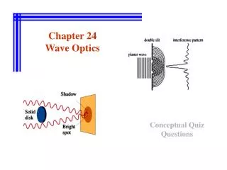
Wave Optics
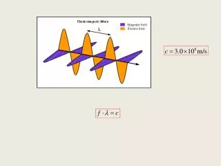
Wave Optics. Unit 11. Light. In the last unit, we studied several properties of light, including refraction and reflection. However, these were geometric properties, and had nothing to do with the fact that light is a wave. Now we will no longer be able to ignore this reality. Interference.

Wave Optics
E N D
Presentation Transcript
Wave Optics Unit 11
Light • In the last unit, we studied several properties of light, including refraction and reflection. • However, these were geometric properties, and had nothing to do with the fact that light is a wave. • Now we will no longer be able to ignore this reality.
Interference The Double-Slit Experiment
Interference • One of the most conclusive examples of the wave nature of light was the Double Slit Experiment. • Early physicists, such as Newton, had thought of light as a particle. • However, Thomas Young was able to show light acts as a wave, and was even able to measure the wavelength of visible light.
Interference • Young created a setup that allowed light from a single source to fall on two closely spaced slits. • If the particle picture of light were correct, we would expect to see two bright lines on a screen placed behind the slits.
Interference • However, instead a series of bright lines were observed on the screen. • Young explained this effect as a wave-interference phenomenon.
Interference • To see how this effect occurs, let’s consider Young’s setup. • Plane waves of light with a single wavelength are striking the slits. • Light of this type is called monochromatic, meaning “one color.”
Interference • When the waves strike the slits, they spread out in all directions on the other side. • This is analogous to what happens when two rocks are thrown into a pond, or when two speakers are placed close together.
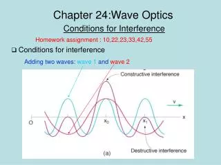
Interference • Recall from the speaker problem that the waves from the two slits will have traveled different distances depending on where they strike the screen. • As a result, the waves may arrive out of phase. • This can lead to interference when the waves add back together.
Interference • Let’s consider monochromatic light with wavelength λstriking slits S1 and S2, which are separated by a distance d. • If we look at the center of the screen, we see a bright spot.
Interference • This is not surprising since the light from each source travels the same distance. • The two waves arrive at the screen in-phase, resulting in constructive interference. • The brightness of the spot is brighter than the light from either slit.
Interference • Likewise, if we look at certain points on the screen that are off the axis, we also see a bright spot. • These are also points where constructive interference is occurring.
Interference • From our experience with sound waves, we know that this means the path length difference must be some multiple of a wavelength. • We will quantify this in a moment.
Interference • At other points, no light can be seen. • These points indicate destructive interferenceis occurring. • The path length difference must be a multiple of a half wavelength.
Interference • To develop a formula for determining the location of the bright (or dark) fringes, let’s look at the geometry of the system. • We want to know how far each ray will have to travel to reach a point at an angle θ above the center.
Interference • Notice that ray 2 travels farther than ray 1. • This is the path length difference. • Notice also that if forms a side of a right triangle with the spacing between the slits.
Interference • Based on this, we can use trigonometry to write the path length difference in terms of d and θ, quantities we can easily measure:
Interference • This gives us the formula for constructive interference:
Interference • This also gives us the formula for destructive interference:
Interference • Notice also that there is a second right triangle that involves the distance from the center on the screen. • From this we can see that
Interference • This lets us rewrite our formulas:
Notes • These formulas are only valid when the distance between the slits (d) is very small compared to the distance to the screen (L). • As a result, θ must be very small. • The value of m is called the order of the interference fringe.
Example Two slits are 0.1 mm apart and are located 1.2 m from a viewing screen. Light from a He-Ne laser beam (λ = 633 nm) is shined on the slits. a)How far from the center is the second order interference minimum located? b)What angle above the horizontal is this?
You Try The He-Ne laser from the last example is replaced with a new laser. You measure the location of the first order interference maximum to be 0.6 cm above the axis. What is the wavelength of the light being emitted by this laser? Express your answer in nm.
Homework • Read 24-3. • Do problems 1, 2, 3, and 5 on page 692.
Announcements • Paper final draft due next Monday. • Presentations May 2 – May 5.
Problem Day • Do problems 5, 10, and 11 on page 692. • We will whiteboard at the end of class.
Homework • Read 24-1 and 24-5. • Do problem 12 on page 692.
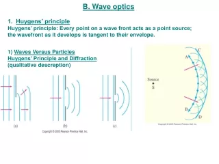
Huygens’s Principle • Christian Huygens was a Dutch scientist who lived about the same time as Newton. • He proposed a wave model for light that is still used today to describe many phenomena. • Recall that for 2D and 3D waves, we describe the position of the wave using the wave front.
Huygens’s Principle Every point on a wave front can be considered to be a source of tiny wavelets that spread out in the forward direction at the speed of the wave itself. The new wave front is the envelope of the wavelets.
Huygens’s Principle • Note that this is a model of how a wave propagates. • However, it is extremely useful for explaining phenomena such as diffraction.
Diffraction • In 1819, the French scientist Augustin Fresnel used Huygens’s principle to explain how light could “bend” around the edges of solid objects. • This phenomenon is known as diffraction. • As we will see in a moment, diffraction produces results similar to interference. The two effects are related, but are not the same.
Diffraction • Fresnel considered a circular disk that was illuminated by monochromatic light. • Using Huygens’s principle, we can consider the points around the edge of the disk to be point sources of wavelets.
Diffraction • These wavelets spread out in all directions. • On the outside of the disk, the wavelets add together with other parts of the beam.
Diffraction • However, the wavelets that spread out toward the inside of the disk, do not encounter each other until they reach the screen. • Thus, Fresnel predicted a bright spot at the center of the shadow of a disk.
Diffraction See also the pictures on p 673.
Question • What effect do those bright/dark fringes remind you of? • In fact, these fringes are due to the interference of the diffracted light waves with themselves. • The image as a whole is called a diffraction pattern.
Single-Slit Diffraction • To see how a diffraction pattern arises, we will consider the simplest case of monochromatic light passing through a single, narrow slit. • We will assume the rays striking the slit are parallel and the viewing screen is very far away.
Single-Slit Diffraction • From Huygens’s Principle, we can model the slit as being made up of a bunch of point sources. • These sources send out wavelets in all directions.
Single-Slit Diffraction • For the wavelets that continue on straight ahead, all the waves travel the same distance to the screen. • This means they arrive in phase and interfere constructively, producing a bright spot.
Single-Slit Diffraction • However, if we move off axis by an angle θ, then the rays from the top of the slit will have to travel a longer distance than the rays from the bottom. • This leads to interference at the screen.
Single-Slit Diffraction • Consider first an angle where the top ray travels one λ farther than the bottom ray. • This means the middle ray will travel λ/2 farther than the bottom ray.
Single-Slit Diffraction • This means the middle ray will interfere destructively with the bottom ray. • The ray just above the bottom will interfere destructively with the ray just above the middle.
Single-Slit Diffraction • Thus all the rays interfere with each other at this angle. • The result is a dark spot on the screen.
Single-Slit Diffraction • If we increase the angle so that now the top ray travels 3λ/2 farther than the bottom, we still get some destructive interference. • The bottom 2/3 of the light from the slit cancel out as before.
Single-Slit Diffraction • However, now there are no rays to cancel the light coming from the top third of the slit. • This light reaches the screen, resulting in a bright spot.
Single-Slit Diffraction • If we increase the angle further so the path difference is 2λ, we get total destructive interference again. • The bottom fourth cancels with the second fourth and the third fourth cancels with the top fourth.
Single-Slit Diffraction • The result is a diffraction pattern with a central bright spot and several dimmer spots seen as you go off the axis in either direction.
Single-Slit Diffraction • To locate the diffraction minima, we need to look at the geometry again. • Notice that, as with the double-slit, the path difference is equal to Dsinθ, where D is the width of the slit.