Download
1 / 49
490 likes | 502 Views
This article provides an introduction to the passive gamma emission tomography (PGET) method for nuclear safeguards. It discusses the motivation behind PGET, the project history and timeline, prototype hardware and software, test campaign results, and future directions. The article also highlights the strengths of PGET and its importance in verifying nuclear material safeguards.

E N D
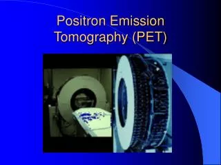
Passive gamma emission tomography (PGET) Tapani Honkamaa
Contents • Introduction • Description of the method • Motivation • Project history and timeline • Prototype Hardware • Prototype Software • Results from the test campaigns • Summary and future directions
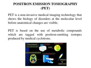
Introduction • Research on Passive gamma emission tomogropgy (PGET) started already in 1980’s • R&D has been and is conducted specifically under R&D programmes made for the IAEA nuclear material safeguards and financed my its member states safeguards support programmes • Hungary, • Sweden • USA, • Finland • EC
Description of the method rotation fuel assembly scanning direction scanned section
And with more detectors arranged in 2 heads: Head1 Head2 104 detectors Tungsten collimator Housing Heads consist of detectors and multislit tungsten alloy collimator With sufficient number of detectors need for lateral movement is eliminated and only rotational movement is needed Detector spacing 4 mm, resulting in 2mm resolution.
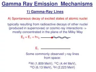
Geometry Head1 Head2 Main signal: 1274 keV Fission product Eu-154 Gamma-ray -compton edge. 104 detectors CdTl 2x5x10mm Tungsten collimator Housing Requirement: imaging of Spent nuclear fuel assembly PWR type 17x17 rods in rectangular lattice Resulting to the need 2 heads, 104 detectors in each, detector spacing 4 mm, resulting in 2mm overall resolution.
Data production and imaging Projections at several angles Measurement (scanning) Fuel Assembly Cross sectional image of fuel assembly Image calculation
Strength of PGET • Method is accurate, it is capable of detecting a single missing pin inside a fuel assembly – true partial defect method
Goal of Nuclear Material Safeguards – Never again Picture: Charles Levy, 9th of Aug 1945
What it takes to build a nuclear weapon? • Nuclear material (U or Pu) • Difficult to get. • Main effort in nuclear non-proliferation is put in here! • Other components • Rather easy to get • Information and Expertise • In general, this indormation is restricted by international agreements • Adequate information is available publicly to build a primitive device
…Why verification is conducted in nuclear material safeguards? • In order to prevent proliferation of nuclear weapons spent nuclear fuel in under stringent control all over the world. The control is exercised by international and national inspectorates • International Atomic Energy Agency (IAEA) European Commission and national regulators. • Implementation of non-proliferation regime requires that declarations and reports provided by nuclear operators can be verified. • Verification tools are needed
Why Passive Gamma Emission Tomography? • Current verification tools have quite limited sensitivity to so called partial defects: • Partial defect = part of the fuel diverted to nondeclared purposes • IAEA Policy: a partial defect test with high detection probability on all populations of easily dismountable spent fuel transitioning to storages where re-verification is either difficult or even impossible. • PGET strength is in its extraordinary sensitivity • PGET would be an important component of the tool box of complementary partial defect test devices. • One interesting application: last verification before fuel assemblies are moved into a geological repository for final storage.
Project timeline 2004 2005 2006 2007 2008 2009 2010 2011 2012 2013 2014 Kick-off Specifications PO for arrays Hardware construction Delivery of arrays System integration Ringhals test System repair&integration Ispra tests Olkiluoto Loviisa Reporting Loviisa Ispra Ringhals Ollkiluoto
Software • Two parts: Control Software and Data Processing Software • Control Software, attended • Input: set up of the detectors and detector electronics and fuel information • Output: The unprocessed (raw) data • Control software automatically invokes the data processing software. • Data Processing Software, automatic • Input: Raw data • Corrections are applied to the raw data, diagnostic modules, etc. • Data analysis can be performed automatically • Manual operation is possible for test/calibration. • Output: information whether pins are missing as compared against a set of operator declared information including fuel type – cross sectional image.
Prototype schema.. ….And in real life! Notebook with ports Driver + PSU AIR WATER Array 1 104 detectors electronics MOTOR with position encoder Array 2 104 detectors electronics UNDERWATER HEAD
Some technical issues in system integration • Longest delay was in delivery of detectors. Procurement, 18 mo delivery time, first acceptance test failed • Some problems: detector arrays do not operate reliably, the read out is working only in serial mode, and stepping motor generates disturbances to the detector signals. • Serial readout is a major issue. • With present prototype measurement time is 1-3 h instead of 2-5 minutes
Passive gamma emission tomographic measurements, Ringhals 16-20 Nov 2009
Ringhals tests • Detector failure prevented the measurements • Overheating of one ASIC (each head consists of 4 ASICs, each controlling 26 detectors (4x26=104) • Grounding issues: Stepping motor rotating 2x150 kg arrays takes a lots of Amperes. • Repair took a few months, then recalibrations, putting things together, combating against grounding problems, etc.
Passive gamma emission tomographic measurements, Ispra 11-15 Jul 2012
Measured objects, results • The fuel items were simple 6, 8 and 12 rod objects • Long cooling time, low signal, long measuring times needed • Result: Imaging was successful • The data provided by another array was not satisfactory • However, resolution provided by another array was sufficient • The calibration was not perfect • Did not prevent of having results • The simple objects are not the real test for the usability of the method. • Self absorbtion is negligible. • However, this was the first successful campaign for the prototype.
Ispra conclusions • The simples objects are not the real test for the usability of the method. However, this was the first successful campaign for the prototype.
Passive gamma emission tomographic measurements, Olkiluoto BWR 15-17 Mar 2013
Measured objects, results • The fuel items were 8x8 and 10x10 spent fuel assemblies • Cooling time varied from 3 to 32 y • Result: Imaging was successful, with some artifacts • Again: The data provided by another array was not satisfactory • However, resolution provided by another array was sufficient • The calibration was made better, but yet not at desired level • Did not prevent of having results • First successful campaign for the prototype with real NPP fuel.
Passive gamma emission tomographic measurements, Loviisa 15-17 Jan 2014
Work prior the test • Removing faulty detectors • Recalibration • Analysis software development for VVER fuel (BUTE) • Modified for hexagonal fuel
Fuel • VVER 440 type fuel is hexagonal • Full assembly has 126 rods, center location is always empty • Challenging geometry due to high self-absorption • One assembly out of 6 had missing rods • 5 assemblies measured, one twice
Loviisa Observations • Measurement of one assembly took 2-3 hours, due to complex design of the fuel 120 scans were needed (compared 48-60 for BWR) • The measurement of the fuel with missing pins was repeated due to poor statictics • The system was able to provide image immediately after measurement • In overall the system functioned well, two problems were observed: • A few distorted profiles out of 120 was generated due to HW malfunction: this is not critical for imaging VVER 440 assembly, they were left out of analysis. • Uniformity of measureing channels was not perfect, some corrections were applied during the analysis
Summary and future directions • A Passive Gamma Emission Tomograph has been designed, manufactured and successfully tested under IAEA support Programme task JNT 1510. • System is able to detect missing pin from BWR and VVER-440 assemblies. • Successful tests with PWR fuel are not yet conducted, but simulations predict that the result is most likely successful.
Summary and future directions • Readiness for deployment and availability for real verifications need to be sustained • New project established • Improvement of the electronic readout is a prerequisite • Shorten the measurement times • Next important steps will be to provide unattended operation • More in depth understanding about analysis is needed • Quantitatively evaluate the cooling time and burnup for each fuel rod • Effect of rods with burnable poisons • Work continues now more intensively • Goal is to have the functional, reliable and tested system available by 2023, when final disposal of spent nuclear fuel in Finland begins.