Download
1 / 16
160 likes | 391 Views
Design of the coincidence processing board for a dual-head PET scanner for breast imaging. J.D. Martínez 1 , J. Toledo 1 , R. Esteve 1 , F.J. Mora 1 , A. Sebastiá 1 , J.M. Benlloch 2 , Ch.W. Lerche 2 and N. Pavón 2 1 Department of Electronic Engineering, Univ. Politécnica de Valencia, Spain

E N D
Design of the coincidence processing board for a dual-head PET scanner for breast imaging J.D. Martínez1, J. Toledo1, R. Esteve1, F.J. Mora1, A. Sebastiá1, J.M. Benlloch2, Ch.W. Lerche2 and N. Pavón2 1Department of Electronic Engineering, Univ. Politécnica de Valencia, Spain 2Instituto de Física Corpuscular (IFIC), Univ. Valencia (CSIC-UV), Spain 6th International Workshop on Radiation Imaging Detectors (IWORID 2004)
Outline • Introduction • Positron Emission Mammography (PEM) • Gamma ray detector • Fully digital coincidence processing electronics • Data acquisition board • Conclusions and future work 6th International Workshop on Radiation Imaging Detectors (IWORID 2004)
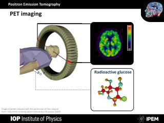
Introduction • Images the radiotracer (β+-emitter) distribution inside the human (or animal) body • Ring of detector blocks (i.e. BGO scintillators + PMTs) • 2D (intraplane) or 3D (intra- and interplane) acquisition modes • LORs (Line-of-Response) joining both interaction points contains the gamma ray source • Images are reconstructed from collected projections • Positron Emission Tomography (PET) Based on detecting 511 keV photon pairs in temporal coincidence from positron annihilations A typical commercial scanner comprises several (normally from 12 to 24) of these rings in the axial direction 6th International Workshop on Radiation Imaging Detectors (IWORID 2004)
Introduction • Functional imaging • CT,MRI: Mostly anatomical • SPECT, PET: Mostly functional • High-resolution scanners (Research areas) • Small animal imaging • Brain mapping • Mammography CT (left) vs. PET (right) images • Pros • Metabolism visualization: highly related with some diseases (i.e. cancer) • Enables quantitative analysis Molecular imaging • Cons (limitations to overcome…) • Poor visual quality of PET images compared with CT or MRI • Moderated resolution (~4 mm in commercial whole-body PET scanners) * Image from IAMA Tutorial http://www.iame.com/learning/PETimagrc/petimage_cintro.html 6th International Workshop on Radiation Imaging Detectors (IWORID 2004)
Positron Emission Mammography (PEM) • Low-energy X-ray screening • Reasonably good sensitivity (~70-90% depending on tissue density) • Limitations • Low specificity for non-palpable lesions (~10-30%) Too false positives • Unnecessary biopsies (traumatic for patients, increases costs of public health policies,…) • Non-intrinsically addressed to cancer detection • Lack of information about metastatic lesions (multi-focality) or lymph nodes affectation • Improvements: Digital radiography Better image quality • Positron Emission Mammography (PEM) • Good approach for addressing and overcome all these drawbacks • 18F-FDG scans provide information about glucose consumption useful for cancer diagnosis (i.e. high radiotracer uptake could imply the presence of malignant lesions) • Enables to detect multi-focality (expected resolution < 2 mm.) and achieves earlier diagnostics • Independent on breast density • Allows to stage breast cancer and study patient response to therapy 6th International Workshop on Radiation Imaging Detectors (IWORID 2004)
Positron Emission Mammography (PEM) • Camera geometries • Dual-head planar • Good solid angle coverage • Easy positioning and breast compression • Incomplete projection data: requires specific reconstruction algorithms (i.e. classical tomography or iterative methods) • Rectangular • Higher solid angle • More difficult to perform breast compression with typical systems • More expensive than planar • Additional projection data but also incomplete • Main challenges • Depth-of-Interaction (DOI) • Parallax error becomes critical due to the nearness of both detectors • Increased count rate • The increased geometrical acceptance and the need of shorter scan times requires the acquisition of more events in less time Dedicated PET cameras enable us to increase resolution and reduce the attenuation focusing the FOV on the area under study 6th International Workshop on Radiation Imaging Detectors (IWORID 2004)
Approach: Continuous scintillator + Pixelated detector Gamma ray detector • Continuous scintillator crystal • LSO • Good light yield • Fast response • Smaller attenuation lenght • Flat-Panel Multi-Anode PS-PMT • Hamamatsu H8500 • 8x8 anode pixel matrix • 50x50 mm2 (49x49 active area) * Photo courtesy of Hamamatsu Corp. • Modified Discretized Positioning Circuit (DPC) [Lerche, 2002] 6 channels • Four position related signals • One signal for DOI computation Second moment of the scintillation light dist. • One signal for the total deposited energy 6th International Workshop on Radiation Imaging Detectors (IWORID 2004)
Fully digital coincidence electronics • Traditional systems limitations • Pulses contain information required in high resolution PET systems • Pulse shape (for example: phoswich schemes for DOI computation) • Pile-ups Above 500 kHz event (or singles) count rate pile-ups become critical • Coincidence timing window Increase temporal resolution by interpolation • Analog detection electronics • Pulse height detection schemes (i.e.: Integration+CFDs) do not allow complete pulse recording • Sequential digital detection electronics (in free-running sampling acquisition) • Generates deadtime when events are processed sequentally • Usually are highly hardware-dependent systems Proposal: A programmable parallel approach without deadtime due to electronics which enables us to record complete pulse shape, improve timing resolution and finally focus processing time on true gamma events (DOI computation, pile-up recovery, scatter rejection…) 6th International Workshop on Radiation Imaging Detectors (IWORID 2004)
Fully digital coincidence electronics • Data acquisition system parallelization • Channels are acquired in free-running sampling • FIFO memories are sequentially written at the same rate • When a block of samples (1024-8192, ~25-200µs) has been stored, a DMA transference is initiated • The DSP processor performs coincidence detection and processes valid events (scatter correction, centroid and DOI computation,…) This architecture avoids interrupt latencies when connecting high speed converters (up to 80MHz) to the DSP processor 6th International Workshop on Radiation Imaging Detectors (IWORID 2004)
Fully digital coincidence electronics • Data flow • Advantages • Not need of timestamps because temporal information is directly the position of the sample in memory • DMA channels do not block DSP processor allowing parallelization • Enables on-line processing Speed-up image reconstruction times • No deadtime due to electronics if tacq > t DMA (and there is enough processing power) 6th International Workshop on Radiation Imaging Detectors (IWORID 2004)
Fully digital coincidence electronics • Coincidence processing system • DSP TMS320C6416 @ 1 GHz (8000 MIPS) Motherboard • 40-75 MHz 12-bit 8-channels ADCs (TI ADS527x) with LVDS outputs (Released in June 2004) • FPGA Virtex-II Pro 2VP4 for deserialization (up to 840 Mbps) and data pre-processing • SDRAM for data histogramming • USB 2.0 (Cypress CY7C68001) I/F Bandwidth up to 45 MB/s 6th International Workshop on Radiation Imaging Detectors (IWORID 2004)
Data acquisition board (Layout) • 8-layer Impedance-controlled PCB • Stack-up • Top (LVDS+USB) • GND • 1V5 • Offset stripline horiz. (signals) • Offset striplne vert. (signals) • 2V5 • Split plane: 3V3D/3V3A • Bottom (signals) • Mixed-signal design (Digital Half-top, Analog Half-bottom) • PCB Technology: 5 mils/ 5 mils (0.127mm/0.127mm) 6th International Workshop on Radiation Imaging Detectors (IWORID 2004)
Data acquisition board • Analog section • 12-channel coaxial inputs (50 ohms) • Single-ended to differential conversion stage • RF transformers provide isolation and performs preliminary pulse shaping • Analog-to-Digital Converters (Texas Instruments ADS527x series) • Deeply integrated (8 parallel ADCs per chip) • Low power (<1W at 40MHz) • LVDS outputs • Digital section • Power supplies • External 3.3V, 1.5V • FPGA 2.5V Linear Regulator • LVDS serial interface (up to 5.6 Gbps data acquisition bandwidth) • Lower noise, reduced pin counts • FPGAs • LVDS desearialization (up to 840Mbps 12-bit x 70 MHz ADCs) • Embedded FIFO memories • Data pre-processing (Digital filtering and processing techniques) • Digital Baseline Restoration (BLR) • Coarse-window coincidence pre-detection 6th International Workshop on Radiation Imaging Detectors (IWORID 2004)
Data acquisition board • Digital Signal Processor (DSP) • Texas Instruments TMS320C6416 (1GHz clock rate @ 8000 MIPS) • VLIW processors with 8 parallel ALUs • 64 / 16 External Memory InterFace (EMIF) buses • Event processing • Coincidence detection • Height comparison • Pulse interpolation (improves timing resolution) • Energy windowing and scatter correction • Centroid computation • From X+, X-, Y+ and Y- channels • DOI Look-up table reading • From DOI-related signal • Acquisition mode • Histogramming • List-mode • Focal plane tomography • Medium quality, fast reconstruction (i.e: useful for FOV centering) Monte Carlo simulation of a breast phantom, 30 min after 10mCi 18F-FDG. Four hot lesions of 10, 8, 4 and 2 mm have been simulated 6th International Workshop on Radiation Imaging Detectors (IWORID 2004)
Data acquisition board • High-speed digital design issues Fast rise times (~500 ps) generates transmission line effects IBIS simulation of longest nets detects problems which can be solved by properly terminating bus traces, tuning lenghts, matching impedances… Over- and undershooting corrected using source terminations (value obtained by simulation) 6th International Workshop on Radiation Imaging Detectors (IWORID 2004)
Conclusions and future work • New high resolution PET scanners require specifically designed electronics which addresses its main challenges • A data acquisition and signal processing system for fully digital coincidence detection and processing has been designed and implemented • We will have first experimental results using breast phantoms in September 6th International Workshop on Radiation Imaging Detectors (IWORID 2004)