Download
1 / 42
420 likes | 661 Views
A monolithic block detector design for a dedicated brain MR-PET scanner. Karl Ziemons Forschungszentrum Juelich, Germany Member of the Crystal Clear Collaboration. 09. Oct. 2009 | ICATPP, Como-Italy. Outline. ClearPET Project F rom a pixelated to a monolithic tapered block concept

E N D
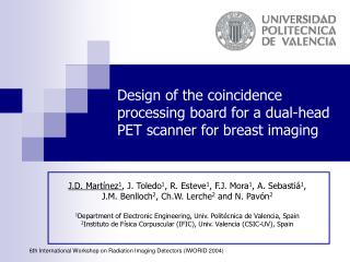
A monolithic block detector design for a dedicated brain MR-PET scanner Karl Ziemons Forschungszentrum Juelich, Germany Member of the Crystal Clear Collaboration 09. Oct. 2009 | ICATPP, Como-Italy
Outline ClearPET Project From a pixelated to a monolithic tapered block concept TOF – Time-of-Light Hybrid imaging concept: MR-PET Conclusion
Challenges in PET • fundamentals: • to obtain as many counts as possible high sensitivity • to localize these counts as accurately as possible high spatial resolution • high temporal resolution
ClearPET™ Project R&D of 6 more or less identical small animal PET scanners • Flandern (VUB a. Hosp. Gent) • Jülich (FZJ) • Lausanne (IHPE) • Lyon (CERMEP / UCBL a. CERN) • Raytest GmbH (Straubenhardt, Germany) • Samsung Medical Center (Seoul, Korea) in collaboration with the Crystal Clear Network (CCC) all scanners are called:ClearPET+extension
ClearPET™ Prototypes ClearPET Rodent(VUB & Hosp. Gent) ClearPET Prototype (Lausanne now Marseille) ClearPET Petite (Samsung Med. C., Seoul)
ClearPET™ Neuro Scanner @ fz-juelich.de @ Institute of Medicine, Forschungszentrum Jülich
ClearPET™: The Innovations • LSO & LuYAP crystals in a dual layer phoswich solution longer crystals improve the efficiency & estimate depth-of-Interaction for a better radial resolution • New concept implement into the frontend electronic:„Free Running Sampling“ mode allows digital pulse processing to identify the crystal layer & extrapolate timing and energy information • Modular design to realize different geometries Crystal block: 8*8 LSO & LuYAP crystals, each 2*2*10mm3 coupled to multichannel PM
Depth Of Interaction in Principle: parallax effect → decreases the radial spatial resolution information about the crystal layer → improves the radial spatial resolution
ClearPET™ properties • Spatial resolution: • System peak sensitivity : 3.5% • Energy resolution ≈ 24% • Time resolution 5.5 ns FWHM 1.4mm 1.6mm 1.2mm 1.8mm 1.0mm 2.0mm Derenzo phantom: Ø 40mm, filled with ~ 0.5mCi, 18F 6min scan time; 3D OSEM reconstruction
Beyond ClearPET™: Next Steps • from a pixelated to a monolithic block concept • Increase sensitivity (no inter-crystal separations, reduced dead space) • 3D position information embedded in the light distribution • extract parallax-corrected incidence coordinates with good accuracy • continuous coordinates • easy to manufacture and to assemble
Beyond ClearPET™: Next Steps • from a pixelated to a monolithic block concept Geometry design of the ClearPET Neuro Geometry design of the BrainPET @CIEMAT System peak sensitivity: > 15% (by the same geometry as the ClearPET Neuro) Spatial resolution: < 1.3mm over the whole FOV Energy resolution: ≈ 11% Goal:
Monolithic scintillator detectors x front Light distribution depends on the entry point on the front surface… z crystal light sensor back and on the depth of interaction (DOI).
Technical Developments • APD detector arrays • Insensitive to magnetic field • Higher QE as PM but lower gain • compact • miniaturization of electronics • Multichannel preamplifier chips • Analog and digital preprocessing with FPGA’s (field programmable gate arrays) or ASIC’s (application specific integrated circuit) S8550 Hamamatsu APD array
Block Configuration for Experimental Setup 20x20x50 mm BaF2 crystal • readout with two S8550 APDs • monolythic 20x20x10 mm3 LYSO:Ce crystal • Light Yield: 32000 photons per MeV of deposited energy [*] • optical photon spectrum: = 420 nm (maximum) • attenuation lenght for 420 nm photons: 420 mm [*] • refraction index: 1.81 [*] • crystal block wrapped by Teflon • reflection coefficient: 0.95 [*] • optical coupling between LYSO:Ce and APD epoxy window 0o - 90o Lead 32x cathode signal 22Na APD matrix PMT Rotation table S LSO crystals AND High precision X-Y stage Coincidence Trigger [*] data taken from product datasheet St Gobain
(y = +5.0) (y = +3.0) (y = +1.0) (x = +1.0) (x = +3.0) (x = +5.0) (x = +7.0) (x = +9.0) (x = -9.0) (x = -7.0) (x = -5.0) (x = -3.0) (x = -1.0) (y = -1.0) (y = -3.0) (y = -5.0) (y = -7.0) (y = -9.0) Experimental results collimated beam scanned over X and Y
Parallax correction during training Photo detectors Train neural network to reproduce the DOI independent incidence position A
Performance of APD-based systems • 20x10x10 mm LSO block read out by S8550 Hamamatsu APD array • 1.5 mm FWHM average resolution • 0.4 mm FWHM degradation at 30o incidence • 11.5 % energy resolution • ~ 2 ns FWHM time resolution
BrainPET laboratory prototype detector blocks rotating source holder two detector blocks aligned face to face 400 mm apart rotating precision source holder for tomographic imaging
BrainPET prototype performance • single 1.0 MBq 0.25 mm diameter Na-22 source • images acquired for a single source at two positions 6.0 mm apart along radial direction • individual images superposed to calculate profiles and spatial resolutions • Image size: 32 mm 32 mm (64 64 pixels), 0.5 mm slice thickness • Reconstruction: 3D SSRB + 2D FBP with ramp filter at half the Nyquist frequency • Visualization: 3D rendering with AMIDE viewer
SiPMorGeigerMode-APD: a newphotodetector Courtesy by C.Jackson, SensL
SiPM: Saturation Effect • The output signal is proportional to the number of fired cellsas long as NPh < Ncells B.Dolgoshein, NIM 2003
LinearityMeasurement Courtesy by C.Jackson, SensL
SiPM Array SensL SPMArray 3035G16: Pixel Chip Area 3.16 x 3.16 mm2 Pixel Active Area 2.85 x 2.85 mm2 Operating Voltage (typical) 29.5 V +2V above Vbr, λ = 520nm Array Details 4 x 4 Pixel Microcell Gain >1x10⁶ - Total Pixel Effective Area 13.4 x 13.4 mm2 Number of Microcells 3640 Per pixel Photon Detection Efficiency 10-20 % 1V to 4V above Vbr Dark Rate 8 MHz Per pixel
Influence of pixel size • Simulation study of a 20x20x10 mm LSO block read out by a pixelated photo detector. • Perfect detection of scintillation photons
Expected performance of SiPM array design • Array Size : 8 x 8 • Pixel size : 3 mm x 3 mm • Pixel Pitch : 3.4 mm • Detection eff. : 30 % • Cell size : 100 µm x 100 µm • Crosstalk : < 20 % ∆E = 8.7 % FWM
Beyond ClearPET™: Next Steps • TOF – Time of Flight PET • Can localize source along line of flight • Time of flight information reduces noise in images • Variance reduction given by 2D/cDt. • 500ps timing resolution 5x reduction in variance
Adding Time-of-Flight to Reconstruction Faster Convergence Data courtesy by W.Moses • Conventional: • Detected event projeted to all voxels between detector pairs • Lots of coupling between voxels • Many iterations to converge • Time-of-Flight: • Detected event projeted only to voxels consistent w measured time • Little coupling between voxels • Few iterations to converge
Whole Body – Time of Flight Simulation Data courtesy by Mike Casey, CPS Innovation Clear improvement of contrast enhancement visually!
LaBr3:Ce3+ with SiPMs: First results(data from D.Schaart et al., IEEE Oct.2008) 3 x 3 x 5 mm3 LaBr3:Ce3+ on 3 x 3 mm2 Hamamatsu S10362-33-025C SiPM Coincidence timing spectrum (two LaBr3:Ce3+/SiPM detectors) 22Na pulse height spectrum
Beyond ClearPET™: Next Steps • Hybrid imaging concept: MR-PET PET & MRI are medical imaging techniques that in widespread use both for patient diagnosis and management, and in clinical research playing a key role in a wide range of fields from mapping of the human brainto the development of new treatments for cancer
Complementary Nature of MRI & PET Hence: The Sum of PET and MRI should be excellent and even better MRI + PET << MRI-PET
Why MRI-PET Hybrid Imaging? • Want true simultaneous data acquisition in a single device • Want combined functional and morphological data acquisition at the same time • Want multi modal functional acquisitions at the same time (fMRI / MRS - PET) • Want to cross-validate activations measured with PET and fMRI under the same conditions, at the same time, in the same status but still want quantitative PET image MRI
Installed in Jülich in autumn 2008:MAGNETOM Trio with a BrainPET
Our first MR-FDG-PET images 20-50 min p.i. 18FDG-PET AW-OSEM3D filtered with 2.5 mm Gaussian Simultaneous T1 MPRAGE Fusion
Beyond ClearPET™: BrainPET Project SiPM PET insert based on monolithic block design: Design of SiPM PET insert Hand made housing of the PET insert including the gradient coil Aim: Development and implementation of a hybrid 9.4Tesla MR-PET animal / human scanner
Summary • BrainPET insert is being developed using monolithic LSO blocks and S8550 Hamamatsu APD arrays • Using an array of 3x3 mm SiPM pixels to read out monolithic LSO blocks has • similar spatial resolution than APDs (~ 1.3 mm FWHM) • slightly better energy resolution (8.7 % versus 11 %) • better timing resolution (sub-nanosecond versus 2 ns with APDs • Detection efficiency is the most important SiPM parameter to optimize • Compared to APDs • signals are easier to handle • we can add more rows or columns because amplifier noise is negligible • Future : Experimental studies using SiPMs and monolithic scintillator in preparation of a fully MR compatible PET insert with high resolution and high sensitivity performance.
Conclusion PET/CT was a medical revolution and a technical evolution MR/PET seems to be a technical revolution and a medical evolution
Acknowledgments Thank‘s to P.Bruyndonckx and S.Tavernier @VUB, Belgium J.Perez and P.Rato Mendes @CIEMAT, Spain H.Larue, C.Parl, M.Streun (ZEL) N.J.Shah, H.Herzog and U.Pietrzyk (INM) @Forschungszentrum Jülich and all the CCC members