Download
1 / 30
300 likes | 510 Views
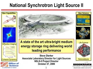
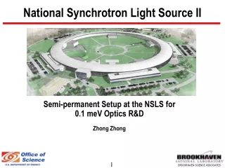
National Synchrotron Light Source II. Status and Progress of 0.1meV R&D at NSLS-II Xianrong Huang, Zhong Zhong, Yong Cai Thanks to Yu. Shvyd’ko (designer, APS) , S. Coburn (BNL), D. P. Siddons (NSLS), A. Baron (RIKEN), C. Kewish (APS), A. Macrander (APS), J. Hill (BNL)

E N D
National Synchrotron Light Source II Status and Progress of 0.1meV R&D at NSLS-II Xianrong Huang, Zhong Zhong, Yong Cai Thanks to Yu. Shvyd’ko (designer, APS), S. Coburn (BNL), D. P. Siddons (NSLS), A. Baron (RIKEN), C. Kewish (APS), A. Macrander (APS), J. Hill (BNL) and all contributors Feburary 7-8, 2008
Outline • Angular Dispersion Optics: Principles and Designs • R&D Progress: Modeling, developing dynamical theory programs Revisit Shvyd’ko’s preliminary experiment of CDW prototype Set up semi-permanent R&D facilities at NSLS 0.7 meV prototype development... • Technical challenges and possible solutions • Exploring alternative approaches • R&D schedule and resources
0.1-meV-resolution Spectroscopy Inelastic X-ray Scattering (IXS) spectroscopy for low-energy photons (5-10keV): • More photons from undulators while IXS is extremely flux-hungry • Better momentum resolution for the same acceptance angle • Stronger scattering cross section, better match to sample size • Extend high-resolution IXS to low- and medium-energy SR facilities (e.g. NSLS-II) • ... Si (008) backscattering E = 9.1 keV Unfortunately, lower-energy IXS conflicts with the principles of backscattering analyzers and monochromators — spectral Darwin widths of low-index Bragg reflections are too large, E> 20 meV. Solutions: Select a small portion of the spectrum New Angular Dispersion Optics
I. Principles of Angular Dispersion Optics Polychromatic Dispersion maximized inGrazing Backscattering: Asymmetric angle =const where Rigorous ! Dispersion in asymmetric diffraction: Different wavelengths diffracted along different directions Si (008), EH 9.1 keV e= 3 rad, = 89.6 E = 0.1 meV Resolution determined by and e Independent of spectral Darwin width
Implementation for 9.1 keV: Basic components(Yuri Shvyd’ko’s designs) In-line CDDW Backward CDW h = 500 m 1 meV L = 12 cm 0.3 meV L = 38 cm 0.1 meV L = 140 cm h = 50 m 1 meV L = 1.2 cm 0.3 meV L = 3.8 cm 0.1 meV L = 14 cm Si (220) Transmission through thin crystals due to Borrmann effect
Dynamical Theory Calculations R Completely verified the principles 1.7 same crystal lengths and parameters
Unique property: Acceptance ~100 rad C/W • Wide acceptance due to collimating by C crystal. • Does not place stringent requirements on stability of incident beam. Works for divergent beam (so can be used as analyzers). = 89.5o 1= 1.0o Acceptance = 140 rad CDW and CDDW both have large acceptance up to 200 rad
DuMond Diagram E DE ~ 0.1 meV Incidence q1 Acceptance ~ 100 mrad
Focused–beam Mono and Analyzer Major difficulty: Long D crystal length L For beam height h = 0.5 mm L ~ 1-2 m ! Possible solution to shorten L: Using slightly focused beam h < 50 m L ~ 10 cm utilizing wide acceptance Analyzer side: it is important to develop precise Multilayer Mirror to improve efficiency Monochromator Analyzer
Parallel–beam Mono with Channel-cut < 5 mrad Better resolution function
Energy Tuning Energy scan within the spectral width E = 34 meV of the backscattering through Rotation of the D crystal in CDW Rotation of both D1 and D2 in CDDW Out of E range, energy scan is through temperature scan of D crystals rotating fan W
0.1 meV spectrometer: Layout Or Large-acceptance Focusing mirror 1 for reducing the beam size Choice of Analyzer depends on focusing condition: 1. Segmented CDW (L ~ 20 cm for each segment) if beam size > 0.1 mm 2. A single CDDW with L < 20 cm if beam size < 0.1mm Developing Multilayer Mirror is important
Main Features of CDW and CDDW • E/EH purely determined by and e (geometrically), independent of EH or of Bragg reflection • For same and e, E decreases with decreasing EH, working better for lower energy • High efficiency (~ 50%) • Wide angular acceptance ~0.1 mrad, working for divergent or focused beam! • Steeper wings (i.e. cleaner resolution function) • For both Mono and Analyzer (analyzer must be combined with collimating mirror) • New but feasible optics with 1-0.1 meV resolution for low- to medium-energy IXS e determined by asymmetric factor b of C/W crystals
II. R&D Progress 1. Modeling optics & developing dynamical theory programs Simulation programs and tools based on rigorous dynamical theory have been developed from scratch, tested to be error-proof • Applicable to backscattering, extremely asymmetric diffraction, transmission, Borrmann effect, ... • Component-orientated, easy plug in (using C++ classes) • For design, spectrum calculation, simulating experiments (alignment, energy tuning), etc These codes have been used to verify quantitatively that the CDW and CDDW schemes work and are efficient at achieving 0.1 meV energy resolution.
2. Revisit Shvyd’ko’s preliminary experiment of CDW prototype DE=2.2 meV E=9.1 keV Yu. Shvyd’ko et al, PRL97, 235502 (2006) SRI (2007) • Successfully observed angular dispersion effect • Darwin width 34 meV narrowed to 2.2 meV Very promising • Why the discrepancy???
X-ray topography of thin W crystals on peak Defects destroy Borrmann effect Problems: • Damages caused by cutting and polishing • Lattice bending caused by machining or weak-linking, broadens E dramatically • Surface roughness (next slide) off peak Lattice is bent (bent part out of the Borrmann effect angular range). Crystal is not acting as a flat wavelength selector Transmission Image taken at 33 BM, APS
X-ray topography (cont.) Reflection topograph taken from the upper surface of W crystal showing surface roughness Topograph of the long D crystal. Almost perfect except scratches. Conclusion:Failure to achieve theoretical performance is mainly due to the bad quality of W crystals, particularly the bent areas that select different wavelengths. Solution: Completely redesign it
3. Redesign W crystal, measure Borrmann effect • Redesign it to an independent component, used in both CDW and CDDW • Transmission through W crystal is due to the Borrmann effect • Experiments underway to measure Borrmann effect and to determine the thickness tand the feasibility of free-standing crystal (next by Zhong Zhong). Our simplified W crystal that works better. Final design will be a free-standing thin crystal for measuring Borrmann Structure factors calculated using Sean Brennan’s program
II. R&D Progress (cont.) 4. Setting up semi-permanent R&D facilities at NSLS 5. Recent progress of 0.7 meV CDW experiments (see next by Zhong Zhong)
III. Technical challenges and solutions D crystal • Lattice constant homogeneity of Long D crystal: ~20 cm per segment, up to 10 segments, but using a strip detector, perfect alignment or precisely the same temperature is not required. Lattice constant homogeneity is required d/d ~ 10-8 throughout each segment Solution: • Acquire highest-quality Si crystals, need accurate measurements before use by the Laue-case lattice comparator setup designed by D. P. Siddons (underway). • Use focused beam (h <50m) to shorten crystals to < 20 cm, down to a few cm Less challenging on Mono side. On analyzer side, depends on development of Multilayer mirrors
Challenges and solutions(cont.) 2. Temperature homogeneity and stability of Long D crystal: < 1 mK, achievable from previous experiments 3. Surface roughness (slope error) for grazing diffraction: • Calculations shows the C/S crystal can tolerate local surface slope error < 0.05º, achievable. • Roughness of D crystal affects the bandwith for grazing angle ~0.5º ( = 89.5º). Edepends on . • Need high-precision fabrication of crystal surfaces, slope error <0.05º. 4. D crystal mounting: Strain-free mounting, no bending of D crystal (< 0.5 rad), achievable. 5. Stability: 0.5 rad stability of D crystals. Thermal coefficient of Si: 2.5610-6 K-1
Challenges and solutions(cont.) 6. Developing high-efficiency multilayer mirrors Large acceptance (~5 mrad), collimating/focusing to <0.1 mrad and 50 m Focusing determining the choice of analyzer and D crystal length. Solution: • Similar mirrors are already achievable at commercial companies. • or R&D effort will be made in collaboration with APS, Spring-8, ESRF etc to develop specifically designed high-efficiency multilayer mirrors. • Mirror efficiency reduce performance but does not affect resolution.
IV. Alternative approaches of 0.1 meV 1. Four-bounce, for both mono and analyzer Acceptance > 100 rad Cons: • Still need long crystals • Efficiency less than CDDW E = 9.3 keV Pros: • More flexible, many variants • Arbitrary energy
2. Multi-cavity Fabry-Perot Interferometer (funded by BNL’s LDRD) Pre-mono 5meV 0.1meV 0.5meV • Multi-cavity FB can increase both Free Spectral Range and Finesse. • Reduce bandwith from ~10 meV to sub-meV • Pre-monochromatization not difficult. • Ultra-compact, single-component, powerful • In principle with no limit neV Si (12 4 0) E = 14.4 keV Courtesy of D. P. Siddions, K. Evans-Lutterodt, A.Isakovic
3. Massive Parallel Analyzer • Concept is similar to back-scattering analyzer. • Each crystal is a small D crystal. • Collimation provided by small beam size on sample, small crystal surface and distance. • Angular dispersion by D crystal allows acquiring all energies by a PSD detector. 0.2 mm Sample 3.5 mm 0.3 mm 1 m 500 pieces, covers 10 rad each 5 mrad total PSD Detector Shielding 0.2 mm
V. R&D Schedule FY 08 — to achieve 0.3 meV • Improve facilities (monos, slits, detectors/CCD camera, motors etc) at X12A • Fabricate crystals and repeat 0.7 meV CDW • Set up temperature-controlled chambers for long D crystals • Measure Borrmman effect to optimize thickness of thin W crystals, repeat 0.7 meV CDW (optics can be used for 1meV endstation) • Build inline CDDW to achieve 0.3 meV resolution • Test monochromatization with divergent beam • Design multilayer mirrors
FY 09 — to achieve 0.1 meV prototype • Full work on CDW and CDDW prototype to achieve 0.1 meV resolution (with limited flux) • Detailed exploration of crystal quality (defects, impurities, inhomogeneities) • Detailed study of fabrication issues (figure error, roughness) • Detailed exploration of temperature control • Develop collimating/focusing multilayer mirrors (collaboration with OFM group at APS, other labs, commercial vendors etc) • Dynamical theory calculations of alternatives (interferometer, four-bounce, multi-crystal analyzer), concentrating on feasibility as analyzer • Test alternative four-bounce design (if necessary)
FY10-FY11 FY10 • Design and develop engineering solutions for adequate temperature homogeneity and stability control • Achieve full-scale 0.1 meV CDW/CDDW components with limited flux • Test and improve collimating/focusing multilayer mirrors • Build and test full-scale CDW/CDDW components (particular mono optics) FY11 • Test and improve analyzer optics with multilayer mirrors (10 x 5mrad2 H&V angular acceptance) • Test alternative approaches • Finalize design
0.1 meV R&D Resources Staff (we are hiring) FY08 FY09 FY10 FY11 Scientist 1.0 1.0 1.0 1.0 Assist Sci 1.0 2.0 2.0 2.0 Post-doc 0.0 1.0 1.0 1.0 Designer 0.5 0.5 0.5 0.5 Crystal Fab Technician 1.0 1.0 1.0 1.0 Crystal Fabrication Equipment • Diamond rough saw • Diamond mill • Lapping machine • Chemical polisher • Table top x-ray source • Chemical hood, cabinet etc Access to NSLS beamlines: • X12A: dedicated R&D • X19C: crystal characterization (regular beamtime) • Many other beamlines at NSLS • PUP at APS
Summary • New optics achieving 0.1 meV resolution at ~9 keV photon energy have been designed for IXS at NSLS-II based on simple and well-established angular dispersion effect in asymmetric Bragg diffraction. • The main optical components are CDW and CDDW mono and analyzer; their detailed operation principles have been proved by rigorous dynamical theory calculations; the CDW mono has been experimentally tested to 2.2meV. • All mechanisms involved are fully understood. • There are technical challenges (e.g. the long crystal issue). These challenges are also well understood and we have feasible solutions (including alternative approaches). • The R&D have already been underway, including detailed theoretical modeling and preliminary experiments. Further R&D are well planned with adequate resources.