Download
1 / 43
440 likes | 683 Views
ACCELERATOR DESIGN OF THE NSLS-II SYNCHROTRON LIGHT SOURCE. W. T. Weng CENTER OF ACCELERATOR PHYSICS, BNL Forum on Low Emittance Intermediate Energy Synchrotron Light Source

E N D
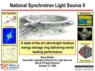
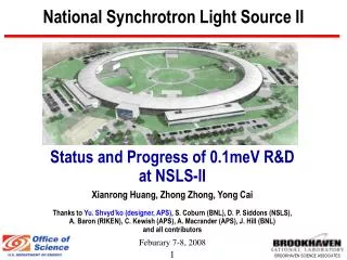
ACCELERATOR DESIGN OF THE NSLS-II SYNCHROTRON LIGHT SOURCE W. T. Weng CENTER OF ACCELERATOR PHYSICS, BNL Forum on Low Emittance Intermediate Energy Synchrotron Light Source August 19-20, 2004 NSRRC, Shin-Chu, Taiwan
ACKNOWLEDGMENT The material presented here are provided by scientists at NSLS, especially Drs. S. Dierker C. C. Kao J. Murphy S. Kramer Zhong Zhong
Present NSLS X-Ray Ring 2.8 GeV 275 mA 80 Operational Beamlines VUV/IR Ring 800 MeV 1000 mA
Diverse Science:Users by Field of Research Largest groups are materials and life sciences Strongest growth in life sciences
National & Regional Resource 2400 Users/year(> 400 academic, industrial, government institutions) New York (32%) Central to BNL programs (16%) International Other Northeast States (27%) (25%) Non-Northeast States Industry: IBM, ExxonMobil, Lucent, pharmaceuticals
NSLS -- I • First Dedicated Second Generation Synchrotron and only remaining second generation DOE synchrotron! • Designed in the 1970’s • Operating Since 1982 • Continually updated over the years - Brightness has improved more than 100,000 fold • However, we are at the theoretical limit with existing ring • Restricted capabilities of present NSLS are increasingly limiting the productivity and impact of its large user community • Major improvements require replacing ring
10+ Year Vision: Enable Grand Challenge Science by Providing World Leading Capabilities What science will users do in 10+ years, and what do they need ? • Soft Matter & Biomaterials Workshop – April ‘02 • 8 Workshops at NSLS Users Meeting – May ‘02 • Ultra-high Resolution X-ray Spectroscopy Workshop – September ‘02 • Low Energy Electrodynamics in Solids Conference – October ‘02 • Microbeam Diffraction Workshop – January ‘03 • 6 Workshops at NSLS Users Meeting– May ‘03 • Scientific Opportunities in Macromolecular Crystallography at NSLS-II – July ‘ 03 • NSLS-II Environmental Science – August ‘03 • Strongly Correlated Electrons: NSLS-II and the Future – August ‘03 • Scientific Opportunities in Soft Matter and Biophysics at NSLS-II – Sept. ‘03 • Biomedical Imaging at NSLS-II– September ‘ 03 • Nanoscience and NSLS-II– October ‘03 • Workshop for NSLS-II– March ‘04 • CD0 Review Feedback, August ‘04
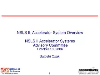
MAJOR DESIGN CONSIDERATIONS • Science Case and User’s Needs, National & International Competition, ( to be covered by C. C. Kao ) • Facility Type: FEL, ERL, SR, SR-ERL • Injector: Linac vs Booster, Top-Up • Lattice: Energy, Emittance, DBA vs TBA, SS • RF: Warm vs Cold, Frequency, Bunch Length, Voltage • Insertion: Superconducting vs PM Undulator, Photon E • Upgrade Path and Growth Potential • R&D Program, Critical Technology • Cost and Construction Schedule
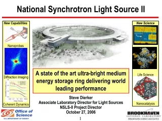
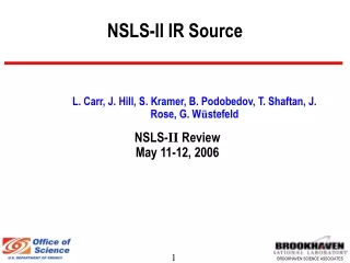
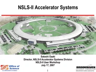
NSLS-II:Ultra-high Brightness Medium EnergyThird Generation X-Ray Ring and IR Ring X-ray Ring • 3 GeV, 500 mA, Top-off Injection • 24 Cell, Triple Bend Achromat • Circumference 620 m • 21 Insertion Device Straight Sections (7 m) • 24 Bending Magnet Ports • Ultra-Low Emittance (ex, ey) 1.5, 0.008 nm (Diffraction limited in vertical at 10 keV) • Brightness ~ 1021 p/s/0.1%bw/mm2/mrad2 • Flux ~ 1016 p/s/0.1%bw • Beam Size (sx, sy) 84.6, 4.3 mm • Beam Divergence (sx’, sy’) 18.2, 1.8 mrad • Pulse Length (rms) 11 psec • Exceptional intensity and position stability • Upgradeable to ERL operation in future Infrared Ring • 800 MeV, 1000 mA, Top-off Injection Highly Optimized X-ray Storage Ring Dedicated Enhanced Infrared Ring
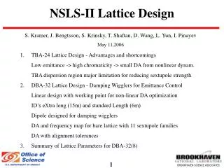
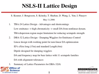
Lattice Design for NSLS-II • Design Goals and Lattice requirements • Choice of Linear Lattice and beam parameters design TBA vs DBA • Dynamic aperture and sextupole tuning • Longitudinal parameters and RF requirements • Impact of undulators on beam parameters • Conclusions and future research plans
WAYS TO LOW EMITTANCE • Small bending, hence long circumference • TBA is better than DBA Cell • Combined function to reduce theta and increase DA • Non-zero dispersion in SS • Proper corrections to increase dynamical aperture • Additional corrections needed for for ID’s
Lattice Design Process User Requirements Short & Long Term Stability Tolerance Errors Lattice Options TBA DBA Longitudinal Dynamics Impact Undulators Linear Lattice Design Non-Linear Distortions Dynamic Aperture tracking
Choice of Linear Lattice Lattice Emittance related to bend angle in dipoles as
Initial Lattice Choice TBA(24) S1 S2 SE SF SD 5 Sextupole Families- 3 Chrom, 2-Harm C=523m, ChromX= -100, Emitt.= 1.5nm
Dynamic Aperture and Sextupole Tuning 5 Sextupole families 3-chromatic and 2- harmonic
Dynamic Aperture from tracking DA > ( 11 x 11mm) Nsigma>( 544 x 7700) Real aperture adequate for injection without breaking periodicity FFT of tracked particles yields real tune shift with amplitude Shows higher order tune shifts dominate > 4-5 mm (4.4um)
Pi-Transformer 2nd Order Cancellation 2nd order geometric terms cancel if identical sextupoles are separated by I.E. Pi - transformer TBA lattice tunes are Qx=1.56 /cell and Qy=0.56/cell this should give partial cancellation. +2 sextupole= 7 sextupole families
Multi-cell Cancellation not Helping 7 families of sextupoles tuned Shows better cancellation But real tune shifts still big And quadratic in Ax and Ay DA not improved
New Direction: Lattice Choice Revisited New user requirement longer undulators and injection straight 7m Quad to Quad length with space for bump in triplet Reconsider lattice choice for TBA
Reconsider DBA(28) 2QF QD QD QF QD High Vertically Focusing Gradient Dipoles Jx =1.45 Zero Gradient Dipoles
DBA(28) Lattice with 7m ID’s Enhanced DBA lattice with high gradient dipoles developed with circumference C= 630m, mostly due to ID length EDBA(28) Achromatic lattice EDBA(28) non-Achromatic lattice
Sextupole Tuning yields large DA Dynamic Aperture increases by minimizing sextupole driving terms DA > (13 x 14mm) DA is large enough to consider injection without breaking 28 period lattice
Momentum aperture also large Chromaticity correction yields +/- 3% with 3Qx resonance at >+3%
Reconsidered TBA(24) Lattice TBA lattice with 7m ID’s and better magnet spacing increased C= 620m, mostly due to ID length
Sextupole tuning harder to optimize Large higher order tune shifts make improvement in DA less predictable with existing expansion of Hamiltonian
Adding a family of sextupoles Adding a 4th family of chromatic sextupoles and linear lattice tuning for reduced horizontal chromaticity yields large improvement in DA > (17 x 7 mm) enough for injection and starting error analysis
Longitudinal parameters and RF The low emittance lattices have major impact on longitudinal parameters of the beam through the small value of the momentum compaction factor. RF Bucket Height Bunch length Momentum Compaction factor ~ Second stable bucket with energy separation When buckets distort and energy acceptance is asymmetric reducing lifetime DBA(28) TBA(24) <- Problem for 3% RF bucket height
Undulator Impact on Lattice Properties Changes of the beam properties were calculated using 4 dipole-2 drift model for undulators in lattice programs Winagile and OPA These have the appropriate rms orbit in the undulators and were compared to analytic models which ignore I4 dependence. Calculated change of lattice parameter for per 2m undulator Tune shift may require some compensation with 20 undulators at Kmax
Conclusions and Future Directions • TBA-24 preferred lattice: Lower emittance (achromatic), ERL and super-bend upgrade potential, lower DA and smaller • DBA-28 Larger DA and emittance, similar emittance (non-achromatic), less upgrade potential • Need to address small DA issues for all lattices: COSY Infinity, PTC, etc. to address nonlinear tune shifts Develop multi-cell cancellation for interleaved sextupole Try octupoles to reduce higher order tune shift with amplitude • Plan to address tolerance errors: alignment, gradient, multipoles • R&D effort: higher gradient dipoles, longer ID’s
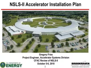
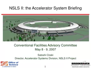
Facility Layout Building AreaArea [SF] First Floor Second Floor Total Linac Vault & Klystron Gallery 12,493 6,068 18,561 Utility Corridor 14,578 14,578 Accelerator Tunnel 51,563 51,563 Experimental Floor 111,230 111,230 Office/Lab 64,173 64,173 128,346 Office Block 11,055 8,945 20,000 TOTAL 265,092 79,186 344,278 IR Ring Office Block Office/Lab Space Experimental Floor Accelerator Tunnel Utility Corridor Linac Vault & Klystron Gallery 60 m Long Beamlines
Siting NSLS Parking NSLS-II CFN N E W S
Average X-ray Brightness NSLSNSLS-IIGain X25 U14 3x10⁴ BM U14 5x10⁶ BM BM 102 X1 U40 103 U5 U100 102-103 NSLSNSLS-II # Und 5 21+ # BM 30 24
Average X-ray Flux NSLSNSLS-IIGain X25 U14 20 BM U14 300 BM BM 2 X1 U40 20 U5 U100 2-3
NSLS-II: World Leading Brightness Current NSLS is off this chart at lower values
NSLS-II Beamlines and Instrumentation Tentative Insertion Device Beamline Plan 5 Macromolecular Crystallography 1 Coherent X-ray Scattering 1 X-ray Micro-beam diffraction 1 Small angle x-ray scattering 1 Materials science/time-resolved 1 Inelastic x-ray scattering 1 Resonant/Magnetic x-ray scattering 2 Superconducting Wiggler (6 beamlines) 4 Soft x-ray undulator beamlines 4 To be determined Optimized and Unique Endstation Instrumentation Automation, Robotics Ultra-High Pressures Ultra-High Magnetic Fields Very Low Temperatures Advanced, efficient, high thoughput, large area detectors Pixel Array Detector
NSLS-II Preliminary Project Profile CONSTRUCTION CO OPERATIONS LLP PED CD Project Engineering & Design Conceptual Design Long Lead Procurement Operations! Construction Commissioning 2005 2006 2007 2008 2009 2010 2011 2012 Fiscal Year FTE –Years : 531 TEC: $393M FY04 TPC: $424M FY04
NSLS-IIThe Future National Synchrotron Light Source Stay tuned for future development Enabling “grand challenge” science