Download
1 / 1
20 likes | 180 Views
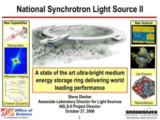
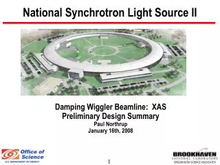
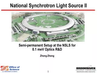
The Development of Laue Monochromator at X17B3 National Synchrotron Light Source in 2006. References:. [1] Z. Zhong, et. al., Acta. Cryst . A 59 (2003) 1-6 [2] J. Hu, et. al. , Eos. Trans. AGU, 84 (46), Fall Meet. Abstract V42A-0334, 2003.

E N D
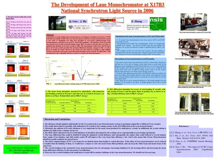
The Development of Laue Monochromator at X17B3 National Synchrotron Light Source in 2006 References: [1] Z. Zhong, et. al., Acta. Cryst. A 59 (2003) 1-6 [2] J. Hu, et. al., Eos. Trans. AGU, 84(46), Fall Meet. Abstract V42A-0334, 2003. [3] Q. Guo, et. al., COMPRES Annual Meeting, 2004. [4] Q. Guo, J. Hu. “The report of X17B3 4-laue monochromator, 2005”. Unpublished letter. Fig. 2-1 0.6mm Si1 (Si-Laue-1) + 0 (Si-Laue-2) Fig. 2-2 0.6mm Si2(Si-Laue-1) + 0(Si-Laue-2) Fig. 2-3 0.6mm Si 3(Si-Laue-1) + 0(Si-Laue-2) Fig. 2-4 0.6mm Si4 (Si-Laue-1) + 0 (Si-Laue-2) Fig. 2-5 ---- 0.6mm Si ---- 4(Si-Laue-1)+1(Si-Laue-2) ; 4(Si-Laue-1)+0(Si-Laue-2) 5. The mono beams testing data on the Image Plate: Fig. 2-1: IP image with Si-Laue-1 has only one crystal Fig. 2-2: IP image with Si-Laue-1 has only two crystals Fig. 2-3: IP image with Si-Laue-1 has only three crystals Fig. 2-4: IP image with Si-Laue-1 has four crystals Fig. 2-5: IP image with Si-Laue-1 has four crystals and Si-Laue-2 has only one crystal at left; while IP image with Si-Laue-1 has four crystals and no Si-Laue-2 at the right. Q. Guo , J. Hu Z. Zhong COnsortium for Materials PropertiesResearch inEarth Sciences Stony Brook UniversityStony Brook, NY. 11794-2100Tel: (631) 632-8213Fax: (631) 632-8140 National Synchrotron Light Source Brookhaven National Laboratory Upton, NY 11973 • The 2-Laue monochromator is using at X17C from 2003 Abstract A prototype 4-crystal sagittal-Laue monochromator was designed, assembled, and tested at X17B3 beam line successfully in 2005. The x-ray flux provided by such four-crystal monochromator system is one order of magnitude less than that provided by two-crystal sagittal-focusing Laue monochromators, currently in use at X17C and X17B3 beamlines. The thickness of the Si crystals was selected to be 0.6 mm to provide design energy 30keV. In order to increase the x-ray flux, we optimized the thickness of Si Laue crystals in 2006. The experimental results show that the three pieces of 0.6 mm crystals provided the strongest diffraction intensity, compared with 1, 2 and 4 pieces of 0.6mm Si crystals. Moreover, the results also show that it is possible to align multiple crystals, cut from the same wafer, to provide monochromatic energy from the 111 diffraction. Such arrangement is also compatible with two-crystal or 4-crystal Laue monochromators. *Introduction of the status of monochromators at X17C and X17B3 in 2005: 1. 2- Si crystal Laue monochromators have been used at X17C and X17B3 successfully by users. 2. The prototype 4-Si crystals Laue monochromator, which was designed and assembler by Z. Zhong, has tested at X17B3 beam line successfully. The thickness of Si crystal was selected as 0.6mm as optimized thick at 30keV x-ray energy. 3. The weakness of flux for 4-Si Laue mono system is the key problem in comparing with 2-Si Laue monochromators, which are used at X17C and X17B3. (See “the report of 4-Laure monochromator testing in 2005” for the details) Y Imaging Plate *The problems of 2-Laue monochromator at X17B3 beamline: 1. The offset of mono beam from white beam at X17C is about 20mm. Therefore it will take one or two days to change it from white beam to mono beam for the diffraction system realignments at X17C hutch. However, it is even not practicable at X17B3 beamline since the laser heating system. It is not easy to realign the laser system in-situ with x-ray. It might be taking another week to do the switches between white and mono x-ray beams as laser heating system in. 2. To lift the whole diffraction optical table at X17B3 hutch 20mm up would fix the mono beam 20mm offset problem. However, there still are some arguments for this: how is about the lifting accurate and how is about the even level at the new position of the optical table? 3. How about the Si crystal optimized thickness is? We should optimize the total thickness of 4 Si crystals as one piece, or should optimize each of the 4 crystals individually? • The prototype 4-Laue monochromator was used at X17B3 in 2005 (011) Fluorescent Plate (011) [2] (111) diffraction Si-Laue-2 [1] Si-Laue-1 Mono beam White X-ray Slits White beam stop Photo Diode Slits X ~2000mm FIG. 1. Laue Monochromator testing setup at X17B3 beam line in 2006 *The 2-Laue monochromator is using at X17B3 with crystal holder modified for mono beam offset shorter • 3. (111) diffraction intensities by severer of non-bending Si crystals, with only having Si-Laue-1 and the photo diode at position [2], as shown as at Fig. 1.(0.6mm thickness and at 30KeV energy): • ========================================================================== • The number of Si Total reading of • Crystals in the stack at the photo diode-2 back ground Net intensity • --------------------------------------------------------------------------------------------------------------------------------- • 1 21.97K 13.5K 8.5K • --------------------------------------------------------------------------------------------------------------------------------- • 2 26.7K 14.6K 12.0K • --------------------------------------------------------------------------------------------------------------------------------- • 3 29.5K 9.6K 19.9K • --------------------------------------------------------------------------------------------------------------------------------- • 4 18.3K 9.6K 8.7K • --------------------------------------------------------------------------------------------------------------------------------- 4. The mono beam intensities, measured by photodiode, with numerous non-bending crystals in Si-Laue-1 and only one Si crystal in Si-Laue-2, as shown as at Fig.1. (0.6mm thick and at 30KeV energy) ========================================================================= The number of Si Total reading of Crystals in the stack at the photo diode-(1) back ground Net intensity -------------------------------------------------------------------------------------------------------------------------------- 1 15.6K 7.5K 8.1K ------------------------------------------------------------------------------------------------------------------------------- 2 19.2K 7.6K 11.6K ------------------------------------------------------------------------------------------------------------------------------- 3 21.8K 7.4K 14.4K ========================================================================= • The 2-Laue monochromator was tested in X17B3 hutch with the • shortest mono beam offset, which results are reported in this poster. • * Discussion and Conclusions: • 1. The thickness should optimize individually for the Si crystals in the Laue Monochromator system to maximum output flux at different X-ray energies. • 2. The results shown that it is possible with multi-pieces Si crystals to have unique energy on the [111] diffraction in the Laue monochromator. • 3. Obviously, the uniform of Si wafer thickness is very important for the mono beam produced by multi-pieces crystals. In additional, the crystal cutting is another key skill to have a unique energy too. • 4. The dE/E will be affected by the Si crystal thickness. It should be determined by the rocking curves experimentally in next testing experiments. • 5. The Laue diffraction flux could be doubled if using the optimized crystal thickness, and consequently, the explore time could reduced to several minutes from couple of ten minutes; and with on-line reader IP will improve the x-ray beam time efficiency a lot. And it also means that 4-Laue Monochromator should be useable routinely for general users. • 6. The NSLS original designs of X17 x-ray beam size are limited about 3mm height at vertical direction. If the offset of Laue monochromator can be reduced to smaller than the limiting of 3mm, we would have a chance to solve the mono beam offset problems, and can keep the white beam and mono beam at the same level. • 7. The crystal bending in the asymmetric Laue monochromators has two advantages: increasing brightness by the focusing effects and increasing the mono beam diffraction efficiency by the non-perfect crystallization. • 8. Moreover, the crystals bending at the multi-pieces crystal will be another challenge at the Laue monochromators. We should test it in next step. Local contact person: Quanzhong Guo. (631) 344-5343, qguo@bnl.gov Welcome comments