Download
1 / 22
220 likes | 375 Views
National Synchrotron Light Source II. Damping Wiggler Beamline: XAS Preliminary Design Summary Paul Northrup January 16th, 2008. Overall Mission. To provide a versatile and highly productive facility for hard X-ray Absorption Spectroscopy for a wide range of scientific disciplines:

E N D
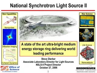
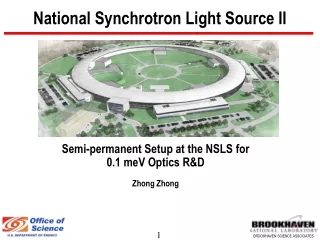
National Synchrotron Light Source II Damping Wiggler Beamline: XAS Preliminary Design Summary Paul Northrup January 16th, 2008
Overall Mission • To provide a versatile and highly productive facility for hard X-ray Absorption Spectroscopy for a wide range of scientific disciplines: • Catalysis and energy science • Environmental science and low-temperature geochemistry • Life science and biology • Nanomaterials and condensed matter research • Earth and high pressure science • To pursue and apply cutting-edge XAS capabilities and techniques appropriate to the advanced quality of the NSLS-II source
Preliminary Design • Careful consideration of: • Community input • User and scientific needs and new opportunities • Technical feasibility • Overall mission of NSLS-II • Through: • Workshops -- local and national • Beamlines’ staff and representatives of scientific communities • NSLS UEC • White papers • Technical, EFAC, and DOE reviews
Beamline Requirements, Specifications • Source requirements: • Broad spectrum, high flux, non-coherent source • Source stability (running in top-off mode): • position within 10% of source size, • vertical angle within 1 rad (for monochromatic energy stability) • Specifications: • Energy range: ~5.5-50 keV, provisions to use up to 90 keV • Tunable spot size from 0.2 x 0.2 mm to 5 x 55 mm • Microbeam (1 x 1 micron) available • Standard (10-4) and high (10-5) energy resolution modes available • Controlled sample environment (air-sensitive or hazardous samples) • Beamline stability scan-to-scan: position on sample within 5 microns, energy calibration within 0.05 eV
Beamline Design -- Overview Top view: Shield wall First Optic Enclosure (FOE) containing beamline optics and white-beam components 2 Experimental Hutches in line Side view: 2 1 Bulk XAS (with three sample positions) Microbeam XAS Beam
Insertion Device • Damping Wiggler, length 3.5 meters, in high-beta straight section • Future upgrade: two canted 3.5m wigglers independently serving microbeam and bulk endstations
Damping Wiggler Characteristics Flux: Brightness: Highest hard X-ray flux at Highest brightness of broad- NSLS-II spectrum sources
Damping Wiggler Heat Load (3.5m) • Wiggler output 32 kW, 4 kW reaches beamline at max acceptance of 0.15 mrad (v) x 1.0 mrad (h) defined by optics • Challenging to maintain broad energy range, stability • “Divide and conquer” approach (absorbs:) • front end mask 25 kW • white-beam apertures 3-7 kW (pass up to 4 kW) • filters and attenuators 1-2.5 kW • white-beam mirror 0-2.5 kW • monochromator first crystal 100-700 W • monochromator second crystal (scatter) • Preliminary thermal analyses show that this can be done • Heat load on sample may be significant (>20 mW)
White Beam Components • Retractable attenuators, sequentially added for higher energy experiments (water-cooled, carbon) • White-beam mirror • 1.5 meter, Si (or GlidCop) substrate, water-cooled • Two “stripes” (bare Si and Pt-coated) available • Three positions: 2.0 or 3.15 mrad, or removed from beam • Thus 5 configurations to cover required energy range • Vertical collimation and harmonic rejection Beam
White Beam Components • High Heatload Monochromator: • LN2 cooled first and second crystals • Side-by-side sets: Si(111) and Si(311) [or Si(333) instead] Beam
Beamline Optics • High energy resolution (10-5 or better) monochromator • In series with high-heatload monochromator • Passes beam when not in use • No LN2 cooling required, high precision mechanism • Several crystal types being considered (less restrictions on material) • Synchronization with primary monochromator is required Beam
Beam Conditioning Optics Focusing mirror (~2:1) • Two toroidal “stripes” match Mirror 1 • Reflects in opposite sense to Mirror 1 • Initial ray tracing calculations: spot size 0.2 x 0.2 mm at sample Beam
Endstation 2: Bulk XAS • Acceptance up to 0.15 x 1.0 mrad • Spot size ~0.2x0.2 mm up to 5x55 mm • Continuous-scan or step-scan modes of data collection • Time-resolved (minutes) studies • 3 sample positions
Endstation 2: Bulk XAS Sample position 1: Classic benchtop XAS • Transmission, fluorescence and grazing-incidence geometries • In-situ measurements: electrochemical cells, gas and solution flow-through cells • Heater, cryostat and LN2 cooling • Standard and high-resolution (energy selective) detectors • Detector for powder XRD pattern
Endstation 2: Bulk XAS 2: Controlled environment XAS • Multi-use enclosure: • Glove box: controlled atmosphere • Containment/fume hood for hazardous samples • Multi-element detector • Low-concentration samples • Hazardous, nano, or radioactive materials
Endstation 2: Bulk XAS 3: Space for move-in apparatus • Large-volume high-pressure or catalytic cells • High-field magnet • Available control and data channels, utilities, etc. • ~2 x 3 m
Endstation 1: Microbeam XAS • Conventional K-B mirror optics • Focused spot ~1 micron • Microbeam and single-crystal XAS • Diamond anvil cell high-P XAS • Multi-use enclosure • Multi-element detector • XRD detector shared with Endstation 2
Estimated flux (delivered to sample at monochromator bandpass) 5.5 keV
Summary: Initial Project Scope • Two endstations included, one control station • Single source and one set of optics serving both endstations • Endstation 2 hutch can be accessed for set-up while Endstation 1 is in use; but not vice versa • Accommodations (space, component design) made for future canting of source • Heatload R&D 2 1
Potential Upgrade/Build-out Path • Add second canted wiggler source and beamline optics to provide independent beam for each endstation • Addition of mirror in front end to divert low-energy portion of overlapped fans into a third station for high-flux bulk 2-6 keV applications • Complementary bulk/micro XAS beamline at adjacent dipole for 1-5 keV applications • Net potential: core cluster of XAS endstations covering 1-90 keV energy range, bulk and microbeam capability 3 2 1