Download
1 / 30
300 likes | 305 Views
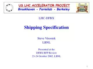
US LHC ACCELERATOR PROJECT. Brookhaven - Fermilab - Berkeley. LHC-DFBX DFBX Production Readiness Review Project Overview Joseph Rasson LBNL 23-24 October 2002, LBNL. Outline. Functional Flow Diagrams Design Variants DFBX Components Engineering Activities Since May 02 Review

E N D
US LHC ACCELERATOR PROJECT Brookhaven - Fermilab - Berkeley LHC-DFBX DFBX Production Readiness Review Project Overview Joseph Rasson LBNL 23-24 October 2002, LBNL
Outline • Functional Flow Diagrams • Design Variants • DFBX Components • Engineering Activities Since May 02 Review • Technical Design Reviews • Design Change Summary • Acceptance Specifications and Travelers • Crating and Shipping Specifications • Project Schedule • Summary
DFBX Functional Flow Diagrams IR Cryogenic and Electrical Distribution Box IP1 & IP5 IP2 & IP8
Design Variants • Eight cryogenic distribution boxes • 6 Slightly different designs with many common components • Major variation results from connection to either cold or warm dipole
DFBX Components Major subsystems: • Power leads: HTS & VC leads • Vacuum vessel • Cryogenic piping • LHe vessel • Thermal shield • Power lead chimneys • Instrumentation leads • Super insulation
DFBX Components (cont.) Other subsystems: • Jacketed beam tube • Bus duct assembly: • Busses • Lambda plate • Bus duct • Interconnect hardware • Alignment tools • Support jacks
Engineering Activities Since May 02 Review Enhanced the Engineering Team in the following areas: • Mechanical design • Daryl Oshatz is leading the mechanical design effort • Added more designers (2 FTEs} • Engineering analysis • Steve Virostek is responsible for structural analysis • Lambda Plate R&D • SUPERCON technician group headed by Roy Hannaford is supporting Jon Zbasnik’s effort • Vapor Cooled Lead • SUPERCON group supporting the mechanical design and layout • Ron Scanlan prepared the lead design specification document
Engineering Activities Since May 02 Review (cont.) Fermilab Engineering Support: • Cryogenic Engineering • Tom Peterson is providing cryogenic design oversight • Don Brown (cryogenic consultant) provided reviewed the design • Interface Specification • Phil Pfund is very active in supporting the interface specification effort • Kerry Ewald is generating mechanical interface drawings • High Temperature Superconducting (HTS) Lead Testing • Sandor Feher will head the HTS testing effort at FNAL
Engineering Activities Since May 02 Review (cont.) Fermilab Engineering Support (cont.): • Procurement Effort • Review procurement documents • Participated in interaction with vendors • Reviewed proposal evaluation effort • Acceptance Criteria • Provided thorough review of acceptance plan • Jim Strait is negotiating the acceptance criteria with CERN
Design Change Summary More Robust Mechanical Design: • Thrust loads and Pipe support • Most of pipe thrust loads were eliminated by use of flex hoses • Bus duct and overflow tank support were modeled and redesigned • Magnet G-10 spiders are no longer load path components • QRL G-10 spiders were simplified and stiffened up • Pipe thermal contraction • Thermal contraction up to 1 inch is possible with flexhoses
Design Change Summary (cont.) More Robust Mechanical Design (cont.): • Helium tank support • Added invar rods for vertical support • Redesigned lateral and longitudinal supports • Modified access panel and rib thickness • Modified weld preps to conform to ASME Pressure Vessel Code • Completed a detailed FEA model • Pressure Vessel Safety Note written and approved by LBNL Safety Committee
Design Change Summary (cont.) More Robust Mechanical Design (cont.): • Optimized thermal shield design and cooling • Added trace cooling channels • Reduces wall thickness of all panels except top panel • Simplified the design by eliminating complex forming • Reduced number of vertical supports • Give vendor more flexibility in forming and attaching panels
Design Change Summary (cont.) Enhance Design for Manufacturability: • More relaxed tolerances • Design intent is conveyed and moved tight toleranced to top level assemblies • Maintained tolerances that are tied to interface specifications • Give vendor more flexibility to manufacture pipe assemblies • Vendor can select construction and fabrication method • Vendor can substitute for elbows, T’s and rearrange routing • Simplify welding and assembly process • Added weld rings to address warping during welding which allows vendor to meet the design intent
Design Change Summary (cont.) Bus Duct and Lambda Plate R&D: • Completed R&D effort • LBNL fabrication and test plan has been developed • Bus duct assemblies will available at the cryogenic system 2 months before the first pair is needed
Design Change Summary (cont.) Beam Tube: • Beam tube cooling jacket design complete • Cold to warm transition layout is underway (to be completed Nov 02) • Bore tubes to be shipped to LBNL (Jan 03) • LBNL to fabricate and test beam tube assemblies then ship them to cryogenic system fabricator • Beam tubes are scheduled to be delivered 3 months before the first beam tube is needed for installation
Design Change Summary (cont.) Current Lead Splice Procedures: • Current lead splice process developed and prototyped • Used the DFBX mock-up to demonstrate the process • Issued purchase orders to the vendors to: • Transfer the technology by training the vendors before the RFP is released • Assess vendors’ capabilities • By making the vendors comfortable with the process, we remove uncertainties that could lead to bids • Roy Hannaford visited the vendors with tools and fixtures to train them • Both vendors showed good capabilities as demonstrated by the samples they produced on their own
Status ofMechanical Interface Specifications • Fermilab is supporting the magnet mechanical interconnect hardware design effort • Not all interconnect hardware proposals have been accepted by CERN yet • Reviewing dipole as-built pipe positions (some are out of tolerance) • Pipe ends will be capped since pressure and vacuum leak tests will be repeated at CERN • Therefore pipes will be fabricated with capped long stubs • Pipe ends will be measured and cut during installation at CERN
Status of the fabrication drawing package • Detailed fabrication drawing package for DFBX-G and C are released • Top level configuration drawings for the other 5 variations are complete • Bill of Materials is complete • All remaining unique pipe drawings ready for release by end of November
High Temperature Super Conducting Leads(HTS) • A total of 40 lead assemblies (20 lead pairs) are required • Full current tests of the prototype pair were performed at CERN in Nov 2001 • Authorized Pirelli to start production in May 2002 • Cold test facility is under construction at Fermilab
High Temperature Super Conducting Leads (HTS) (cont.) HTS Production Schedule: • Pirelli’s initial production schedule slipped 1.5 months • Latest Pirelli schedule as of 21 Oct: 1st 5 pairs @ FNAL Dec. 2002 2nd 5 pairs @ FNAL Jan. 2003 3rd 5 pairs @ FNAL Feb 2003 4th 5 pairs @ FNAL Mar. 2003 • Leads for first box will be delivered to the vendor at least 4 months before they are needed
Vapor Cooled Leads • VC Leads required 16 sets of 600A-3pair 8 sets of 600A-1pair 8 sets of 120A-5pair • Lead design layout was revised to provide more installation clearance • Eliminated Fisher connectors (high cost and long lead time) • Ron Scanlan prepared the performance/design Specification • Specification was reviewed by CERN and FNAL • Design reviewed by vendors in August
Vapor Cooled Leads (cont.) Procurement Schedule: Issue RFQ 7 Oct. 2002 Bidder responses 8 Nov. 2002 Place order 10 Dec 2002 Deliver leads for DFBX-G Apr 2003 2nd shipment@ LBNL May 2003 3rd shipment @LBNL Jun 2003 • Leads for DFBX-G will be delivered to the vendor 3 months before they are needed for installation
Acceptance Specification and Travelerstatus LBNL acceptance from vendor: • Defines the tests and measurements required to meet functional and interface specifications • Defines in process inspection points that give the vendor flexibility in selecting the manufacturing process and assembly sequence • Defines the set of travelers to be completed by the vendor • LBNL final acceptance takes place after pressure and vacuum leak tests are completed at CERN
Acceptance Specifications and Travelers (cont.) CERN acceptance from US-LHC is based on: • Approval of LBNL-vendor Acceptance Specification,mainly: • In-process tests and inspection • Final test/inspection prior to shipping • Inspection and tests at CERN after shipping • Approval of power lead Acceptance Specifications • Approval of LBNL-manufactured components Inspection Specifications • Completing a series of electrical tests at CERN: • Hi pot and continuity tests of leads, bus duct and instrumentation conduits
Crating and Shipping Specification • Requirements based on FEA of shipping package with appropriate safety factors: • Maximum vertical shock acceleration transmitted to DFBX +/- 5.0 g • Maximum horizontal shock acceleration transmitted to DFBX +/- 2.0 g • Free drop from a height of 6 inches without transmitting more than the vertical shock limit of 5.0 g • Crating and shipping specification document has been distributed to the vendors for review by their shipping subcontractors • Vendors feel comfortable with taking on the crating shipping responsibility
Project Schedule • Additional schedule constraints: • US-LHC Accelerator Project Ends September 2005
Project Schedule (cont.) Schedule forecast • Based on the LOI production schedule provided by the manufacturers: • First DFBX Delivered 13 month ARO • Meets CERN requirement • Last (8th) DFBX Delivered 27-29 months ARO • Meets DOE-LHC requirement • However, production schedule is aggressive • To meet schedule extensive oversight is required • Highlights the urgency to get process started
Summary • Design team was enhanced • Fermilab is playing an active role in supporting the design effort • Mechanical design is more robust and simpler to fabricate and assemble • Detailed fabrication drawing package being readied for the RFP • LBNL components will be ready 2-3 months before need dates • HTS production has started • VC leads RFQ is released and order will placed in Dec 02 • Project is ready to start the RFP process • Meeting production schedule is a major challenge