Download
1 / 75
750 likes | 957 Views
DFBX Thermo-Mechanical Review. Joseph Rasson, LBL Tom Peterson, Fermilab CERN 24 April 2007. DFBX Presentation Outline. Introduction Documentation Flow schematic Line pressures Mechanical Test Protocol Piping and Interface Layouts Mechanical Loads Free body and force diagrams

E N D
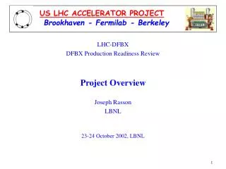
DFBX Thermo-Mechanical Review Joseph Rasson, LBL Tom Peterson, Fermilab CERN 24 April 2007
DFBX Presentation Outline • Introduction • Documentation • Flow schematic • Line pressures • Mechanical Test Protocol • Piping and Interface Layouts • Mechanical Loads • Free body and force diagrams • Peak stresses • Transport • Conclusion • Future Activities DFBX
Introduction • DFBX designed at LBNL and fabricated at Meyer Tool near Chicago Illinois • Fabrication oversight performed by Fermilab • Present team consists of • Joseph Rasson (LBL), project manager • Steve Virostek (LBL), engineer • Frederic Gicquel (LBL @ CERN), engineer • Tom Peterson (Fermilab), engineer • Phil Pfund (Fermilab), engineer DFBX
DFBX Documentation • http://www-td.fnal.gov/LHC/Uslhc_accel_docs/Documents.html • Fabrication documentations for DFBX and LQX. • http://sc-gs.web.cern.ch/sc-gs/gs_ms/TISUS/ • Safety related documentation submitted to CERN. • http://tomato.fnal.gov/lhcirq/DFBXimages/IndexDFBX.html • Pictures of DFBX during fabrication at the vendor. • http://www-eng.lbl.gov/~rasson/DFBX%20DWGS_APRIL_07/ • Drawings of the DFBX. DFBX
Flow schematic • The inner triplet cryogenic flow schematic was developed in close collaboration between • Rob Van Weelderen (CERN) • Jon Zbasnik (LBL) • Tom Peterson (Fermilab). • The following are excerpts from the DFBX G/C and DFBX E flow schemes. DFBX
Overview of DFBX Flow Schemes • 8 DFBX’s, 6 different types • QRL on wall side, so left and right at each location differ in being “left handed” and “right handed” • Points 2 and 8 have the same configuration with cold D1, so DFBX C is identical to G and DFBX D is identical to H. • Points 1 and 5 differ from 2 and 8 in having warm D1 and differ from each other in having opposite slopes. DFBX
Flow schematic for IP8 left Following slide shows the DFBXG detail DFBX
DFBX-G lines with 20 bar design (the largest high-pressure lines) Helium vessel DFBX
Flow schematic for IP5 left Following slide shows the DFBXE detail DFBX
DFBX-E lines with 20 bar design (the largest high-pressure lines) Helium vessel DFBX
Mechanical Test Protocol Tests at the manufacturer (Doc. M989A): • Cold shock all welds at least one cycle • Cold shock chimney bellows 25 cycles • Pressure test all components at set test pressure • Vacuum leak check all components • Final system pressure test and vacuum leak check • Measurements of all critical dimensions Vacuum leak checks and measurement of critical dimensions were repeated at CERN after shipping: See Doc LHC-DFBX-001-10-00 DFBX
DFBX Piping Layout D1 End Q3 End DFBX
DFBX – Q3 Interface DFBX
DFBX – Q3 Interface DFBX
Mechanical Loads • Mechanical loads on the DFBX are Generated from: • Thermal contraction of spool pieces and magnets • Thrust load from bellows (positive and vacuum pressures) • Internal pressure (positive and vacuum pressures) • Gravitational loads (weight) DFBX
Forces from Thermal Contractions • Dominated by contraction of magnet ends away from DFBX • Q3 lines pull back 16.3 mm • D1 lines pull back ~20mm D1 fixed support at Center • Internal DFBX components: Max thermal contractions is ~ 6 mm • Design Approach:Neutralize mechanical forces generated from thermal contraction with the use of flex hoses DFBX
Design Approach for Thermal Contraction Pipes are installed such as flex hoses are preflexed half way when warm. Flexhose moves +/- thermal contraction length Welded ring to carry weight of pipe on G10 Spider Assy Flex hoses to take up thermal contraction and pipe misalignment DFBX
Welded ring to carry weight of pipe on G10 Spider Assy Large diameter flex hose: 50.8 mm Dia DFBX
Gravitational Loads • Weight of most spool pieces is supported on G10 spiders in jumpers • Spiders also provide mean to keep the pipes aligned during and after interconnection • Weight of LHe vessel and bus ducts is transferred to vacuum vessel via 4- 19 mm invar rods (to be discussed later) DFBX
Double spiders in jumpers carry the weights of small pipes and guide/align pipes 12.7 mm thick G10 plates 6.4 mm mm thick G10 split Pipes DFBX
Non Load Bearing G10 Support Spiders D1 End 22.2 mm thick G10 plate 12.7 mm thick G10 plates Q3 End Beam pipe Center support Attached to LHe vessel Bus duct SS support clamps and split rings DFBX
Thrust Loads in DFBX • Limited to components with bellows at the ends for ease of interconnect and to allow for thermal contraction: • XB: Q3-DFBX pumping line • MQX1: Q3-DFBX bus duct • MBX1: D1-DFBX bus duct • LD cross-over line inside the box whenever we have cold D1 (4 boxes) DFBX
DFBX Thrust Loads English Units Si Units DFBX
XB Line with Flow Separator D1 20 mm Thermal contraction Flex hose for alignment Flex hose for thermal contraction Q3-XB Thrust: 4 KN DFBX
XB Supports 3 Gravity Vertical Supports 2 Thrust Supports to vacuum vessel DFBX
XB without Flow Separator 2 Horizontal Thrust Supports One gravitational support DFBX
Bus Duct Assembly: Thrust Load D1: 10.1 KN LD: 6.5 KN Q3: 20 KN Thrust Support Brackets DFBX
LHe Vessel Support DFBX
End view showing helium vessel axial supports and beam tube support DFBX
DFBX-E 17 Feb 05 DFBX
Free Body Diagrams • General diagrams showing approximate magnitude of force • More detailed analysis will be presented at the component level DFBX
Forces on DFBX-E due to pressure of 3.5 bar in the helium vessel plus gravity 66.8 kN (15000 lbf) 635 mm (25.0 in) 767 mm (30.2 in) 16.7 kN (3750 lbf) x 2 (rods in tension) 16.7 kN (3750 lbf) x 2 (rods in tension) DFBX
Forces on DFBX-E due to M1 line pressure of 20 bar plus gravity (no helium vessel pressure) 3.0 kN (680 lbf) x 2 (rods in compression) 4.4 kN (1000 lbf) 20.0 kN (4500 lbf) 635 mm (25.0 in) 10.0 kN (2250 lbf) x 2 767 mm (30.2 in) 5.4 kN (1180 lbf) x 2 (rods in tension) DFBX
Forces on DFBX-E due to 20 bar M1 line pressure plus 3.5 bar in the helium vessel 66.8 kN (15000 lbf) (Combined pressure and gravity) 20.0 kN (4500 lbf) 635 mm (25.0 in) 10.0 kN (2250 lbf) x 2 767 mm (30.2 in) 20.8 kN (4680 lbf) x 2 (rods in tension) 12.5 kN (2820 lbf) x 2 (rods in tension) DFBX
Forces on DFBX-C due to 20 bar M1 line pressure plus 3.5 bar in the helium vessel 82.3 kN (18500 lbf) (Combined pressure and gravity) 20.0 kN (4500 lbf) 10.1 kN ( 2280 lbf) 635 mm (25.0 in) 5.0 kN (1110 lbf) x 2 767 mm (30.2 in) 22.6 kN (5090 lbf) x 2 (rods in tension) 18.5 kN (4170 lbf) x 2 (rods in tension) DFBX
Forces on DFBX-C due to 3.5 bar in the helium vessel 82.3 kN (18500 lbf) 635 mm (25.0 in) 767 mm (30.2 in) 20.6 kN (4630 lbf) x 2 (rods in tension) 20.6 kN (4630 lbf) x 2 (rods in tension) DFBX
DFBX Detailed Analysis • Analysis assumptions and methodology • He vessel supports - stress analysis • Upper, vertical support rods and attachments • Lower, axial supports and attachments • He vessel cover plate weld – stress analysis • Bus duct & thrust support – stress analysis • XB line – load and stress analysis • Vacuum Vessel Bumpers
Analysis Assumptions and Methodology • Analyses assume worst case operating loads • 3.5 bar absolute in helium vessel • 20.1 kN (4510 lb) bus duct thrust load (20 bar) • XB line thrust • 4.0 kN (902 lb) thrust load (4 bar) • Possible added load from D1 line • All components are assessed based on the material and weld allowable limits set forth by the ASME Pressure Vessel Code • Code limits are for guidance and not a hard requirement
Helium Vessel Support Loads • Reaction loads are based on the results of the helium vessel FEA model runs • A portion of the bus duct thrust load is reacted at the stack bellows due to their high lateral stiffness • Vertical strut loads are affected by the moment from bus duct thrust load • The worst case vertical support rod and axial support loads are used for all analyses • Peak axial support load: 8.7 kN (1962 lb) • Peak strut tensile load (Q3 side): 15.9 kN (3570 lb) • Peak strut tensile load (D1 side): 19.6 kN (4414 lb) • Peak strut compressive load: 3.03 kN (682 lb)
Pressure Vessel Code Stress Limits • Material stress allowable limits from code • SS 304L: 115 MPa (16.7 ksi) tensile stress • SS 18-8: 130 MPa (18.8 ksi) tensile stress • Invar: 276 MPa (40 ksi) yield stress (not from code) • PV code limits have built-in safety factors • S.F. ~2 on yield and >4 on ultimate stress • For welds, efficiency factors are applied based on guidelines in PV code • Tensile and shear stresses are combined using von Mises formulation
Lower He Vessel Axial Load Blocks (weld) Calculation Details Material: 304L stainless steel Net axial load: 8.7 kN (1962 lb) Weld size: 9.65 mm (0.38”) Moment arm: 36 mm (1.4”) Weld A: 1560 mm2 (2.42 in2) Weld I: 4.40x105 mm4 (1.06 in4) Tensile stress: 13.4 MPa (1.95 ksi) Shear stress: 5.6 MPa (0.81 ksi) Equivalent stress: 16.6 MPa (2.40 ksi) Allowable stress: 115 MPa (16.7 ksi) Weld efficiency factor: 0.55 Net allowable stress: 63.3 MPa (9.19 ksi) Weld
Lower He Vessel Axial Load Blocks (mat’l) Calculation Details Material: 304L stainless steel Net axial load: 8.7 kN (1962 lb) Moment arm: 36 mm (1.4”) Block A: 2903 mm2 (4.50 in2) Block I: 3.51x105 mm4 (0.84 in4) Tensile stress: 16.8 MPa (2.44 ksi) Shear stress: 3.0 MPa (0.44 ksi) Equivalent stress: 17.6 MPa (2.56 ksi) Allowable stress: 115 MPa (16.7 ksi)
Lower He Vessel Invar Rods and Nuts Rod Calculation Details Material: Invar ½” all thread Net axial load: 4.4 kN (981 lb) Rod stress area: 91.5 mm2 (0.142 in2) Tensile stress: 47.7 MPa (6.91 ksi) Yield stress: 276 MPa (40 ksi) Assume load is shared equally on both sides of 2-sided rod Nut Calculation Details Material: 18-8 stainless steel Net axial load: 4.4 kN (981 lb) Nut shear stress area: 211 mm2 (0.33 in2) (based on load carried by 3 threads) Equivalent stress: 35.9 MPa (5.21 ksi) Allowable stress: 130 MPa (18.8 ksi) Both rods and nuts can carry the full load at one end of the rod if machining and assembly tolerances lead to unequal loading
Lower He Vessel Axial Stanchions Calculation Details Material: 304L stainless steel Net axial load: 4.4 kN (981 lb) Moment arm: 95 mm (3.8”) Area: 1976 mm2 (3.06 in2) Mom. area I: 3.25x105 mm4 (0.78 in4) Bending stress: 28.4 MPa (4.12 ksi) Shear stress: 2.2 MPa (320 psi) Equivalent stress: 28.7 MPa (4.16 ksi) Allowable stress: 115 MPa (16.7 ksi) Peak Stress One stanchion can carry the full load if machining and assembly tolerances lead to unequal loading