Download
1 / 41
420 likes | 438 Views
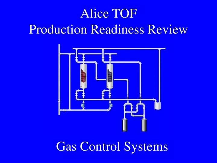
Alice TOF Production Readiness Review. Gas Control Systems. General Philosophy. Modular design – Identification of Gas Modules – Applies to both Hardware and Software

E N D
Alice TOFProduction Readiness Review Gas Control Systems
General Philosophy • Modular design – Identification of Gas Modules – Applies to both Hardware and Software • Electrical and Controls Interfacing Hardware Housed in 3U high 19” Rack mounting Trays – Standardized Layout and Construction – easy relocation of electronics (minimal re-work) • Where Possible, Use of Standard Industrial “Off the Shelf” components • Hardware and Software Well Documented Allowing Work Load to be placed On Other Sections/Outside Contractors.
Component Selection • Industrial PLCs - Schneider (Cern recommended) Quantum & Premium • Industrial distributed I/O modules - Wago • Cern Designed Radiation tolerant ELMB for Flow Cell readout • Industrial Networks – Profibus, CanBus for I/O interfacing • Some Gas Hardware with Profibus Interfaces “built in”. • Ethernet Network (TCP/IP Modbus with UNICOS middleware for PLC to PLC and PLC to SCADA communications)
TCP/IP Modbus Schneider “Premium” PLC Schneider “Quantum” PLC CanBus Profibus Pump Controller Profibus DP Wago Profibus I/O CanBus ELMB Profibus MFC Control System Architecture
Device Interfacing Motor Starer (required above 1 Horsepower) Motor Speed Controller – Direct Profobus Interface Wago I/O Modules with PB Coupler Pump/Motor Flow Switch (DI) Flow Transmitter (4-20mA) PLC with Profibius Module 4-20mA Controlled Power Regulator Isolating Barriers (Used between control system and gas rack when Flammable Gas Present) Pressure Transmitter (0-5V) Pt100 Temperature Sensor Heating Cable
Cabling of Gas Racks Mixer Rack – Profibus daisy chain of 4 mass flow controllers
Cabling of Gas Racks Mixer Rack - Electrical Box
750-301 Profibus DP Coupler 750-402 24V D/I (4 ch) 750-461 Temp. I/P (2 ch) 750-504 24V O/P (4 ch) 750-504 24V O/P (4 ch) 750-402 24V D/I (4 ch) 750-530 24V D/O (8 ch) 750-461 Temp. I/P (2 ch) 750-504 24V O/P (4 ch) 750-600 End Module 750-401 24V D/I (4 ch) 750-530 24V D/O (8 ch) 750-504 24V O/P (4 ch) 750-602 Separation Module 750-461 Temp. I/P (2 ch) 750-554 4-20mA O/P (2 ch) 750-504 24V O/P (4 ch) 750-468 0-10V A/I (2 ch) 750-474 4-20mA I/P (2 ch)
Controls Rack Overview Industrial “Hot Swap” Power Supplies Schneider “Quantum” PLC Schneider “Premium” PLC Control Chassis For CO2 Removal Module Control Chassis For Purifier Module Control Chassis For Mixer Module Control Chassis For Distribution Module Control Chassis For Pump Module (with Frequency Controller Mounted Away From Other Electronics)
Control Rack Bus Distribution N+1 redundant power supply system Main Incoming Power Isolator Miniature Circuit Breaker 3 Phase Distribution 24VDC Distribution Profibus
UNICOS (Unified Control System) • Develoed originally for the Cryogenics systems by GTD Alsthom, and now adapted in a colaboration to enable it to be equally applied to gas systems. • Device Oriented approach to PLC programming, making use of Function Blocks written in Structured Text language • For every hardware “Device” there is an equivalent software object – these objects fit into “classes” e.g. field objects, Process Control Objects etc – instances are created for each device • Each Software Object has an equivalent object at the SCADA system, allowing devices (via the PLC) to fully report states, be taken into manual control, have parameters associated with them, be given interlocks etc
Software Structure GCS ALICE TPC TOP MODULE MIXER PUMP PURIFIER DIST. EXHAUST RECOVERY COLUMN A COLUMN B FIELD OBJECTS I/O OBJECTS
Software Design • URD (User Requirements Document) – Covers All Modules • Generation of State Diagrams • Design Approval • Design Specification (for Each Module) • Design Reviews • Implementation/Coding
Piping & Instrumentation Drawings (P&IDs) and Instrument Identification