Download
1 / 9
90 likes | 195 Views
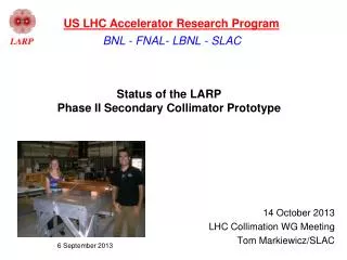
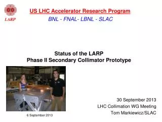
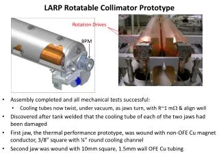
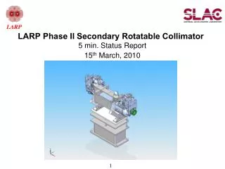
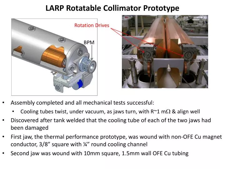
LARP Rotatable Collimator Prototype. Rotation Drives. BPM. Assembly completed and all mechanical tests successful: Cooling tubes twist, under vacuum, as jaws turn, with R~1 m & align well Discovered after tank welded that the cooling tube of each of the two jaws had been damaged

E N D
LARP Rotatable Collimator Prototype Rotation Drives BPM • Assembly completed and all mechanical tests successful: • Cooling tubes twist, under vacuum, as jaws turn, with R~1 m & align well • Discovered after tank welded that the cooling tube of each of the two jaws had been damaged • First jaw, the thermal performance prototype, was wound with non-OFE Cu magnet conductor, 3/8” square with ¼” round cooling channel • Second jaw was wound with 10mm square, 1.5mm wall OFE Cu tubing
Crack in Copper Magnet Conductor Used for Winding First Prototype Jaw Suspect weakening in non-OFE Cu tubing at crystal grain boundaries after last of many high temperature firings Repaired with solder patch Accelerator Systems - T. Markiewicz
Leaks at Tack Welds and Perhaps at Thinned Points in Thinner Walled Tubing Used for Winding 2nd Prototype Jaw Tube walls thinned to 0.030” in places when mandrel prepped for jaw braze Repaired with “CuSil” [possibility this leak introduced during diagnostic cutting] “SNOOP” bubbles at tack welds used to secure tubing: 5 leak points Neither of these procedures are fundamental New assembly process developed to avoid these two procedures
Other Lessons Learned During Prototype Testing • After 5 weeks of bakeout (with the leaking cooling tubes sealed) tank & jaws (& inside surface of tubes pumped through their leaks) reach P=4.4E-9 torr with clean RGA • Rotation mechanism tested after bakeout and works • Other “Less important” lessons learned that will be improved in the next prototype • Replace problematic free floating RF bearings with race-constrained bearing • Capture main bearing so cannot slide off during bakeout • Replace W-S2 440 Stainless coated main bearing with ceramic bearing • 1 of 4 main bearings froze to race during bakeout (W-S2 316 SS bearings all fine) • Replace 1 of 2 molybdenum rotation drives that cracked when spot welded • Non-fundamental issues that will not be changed • Impedance dominated by tank size & simplified 1-dimensional RF transitions • We will not develop BPMs that move with jaws will not be implemented
New Plan Replace both jaws & reinsert into existing base plate with existing vacuum bellows and motion system • We have major parts in-house for 2 complete new jaws Need to • Modify jaw assembly procedure to guarantee cooling tube integrity • Improve the so-called “less-important” lessons learned • Reassemble with rotation drives & test • Re-weld vacuum tank, bake & vacuum test Need to deliver to CERN as soon as possible • DOE has demanded project be finished as soon as possible • Activity supported by SLAC and carry-forward funds (no new DOE $) • Beam and destructive HiRadMat testing schedule will be determined once RC actually arrives at CERN
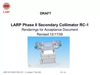
New Assembly and Braze Procedure to Guarantee Integrity of Cooling Coil • Proposed Procedure: • Wrap a 1mm thick OFE copper sheet around the mandrel with its wound cooling tube • Braze material between sheet and OD of mandrel • Braze in 316 SS Compression Fixture to lock down tubes without spot welds • Tubes not touched during machining to true mandrel OD for jaw braze
Lessons Learned from this Prototype • Keystoning an issue • Understand size of the effect & make sure grooves in mandrel match • Sheets of braze material by themselves inadequate • Braze wire should be put on each edge of cooling coil spiral (as was done for 2 previous prototypes) PLUS sheet braze material to bond 1mm sheet to tops of mandrel AND cooling coil • 1mm thick sheet adequate to protect against later machining for jaw braze • KLY braze shop advises us to keep 1mm sheet but to abandon the 316SS clamp, returning to the method use to braze the previous mandrels: moly wire • Decide that a 2nd prototype required before risking the two (ready & waiting) cut & grooved full length mandrels
Other Work in Progress • 45 bar hydraulic test of 1.5mm wall 10x10 tubing • Braze the two new shaft assemblies: