Download
1 / 62
620 likes | 762 Views
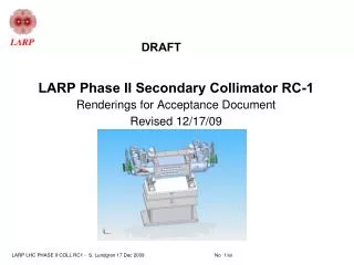
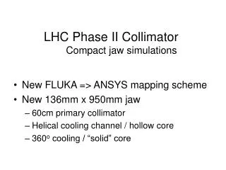
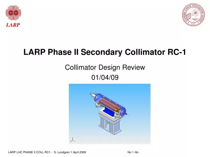
LARP Phase II Secondary Collimator RC-1. Collimator Design Review 01/04/09. Introductory Statements. Your comments and/or questions are welcome at any time . There will also be time at the end for an in-depth discussion of any and all aspects of our design. Sub-title of this talk :

E N D
LARP Phase II Secondary Collimator RC-1 Collimator Design Review 01/04/09
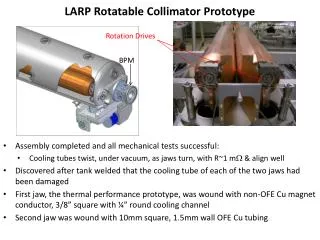
Introductory Statements • Your comments and/or questions are welcome at any time . There will also be time at the end for an in-depth discussion of any and all aspects of our design. • Sub-title of this talk : • “The Rotatable Collimator from the inside out” • Basic format I hope to follow: • Internal component detail (CAD models and photos of real pieces (RC-0 / RC-1) • Fabrication photos of components of the RC-0 Jaw aka Heater test Jaw. • Fabrication photos of some of the RC-1 components that are currently in work. • Specifications and physics requirements and how we meet them.
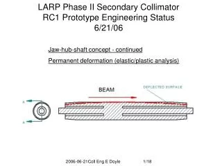
Collimator Jaw-Hub-Shaft Concept Jaw heats up along the side facing the beam and lengthens causing each end to deflect away from the beam and into the 2mm annular gap between the Shaft and the Jaw. The Jaw also swells a bit causing the Jaw face move towards the beam.
Some Calculations • Jaw heating and deflection characteristics for • Steady State (SS) and Transient (TR) conditions • Component SS TR units • Max jaw temp 70.6 224 C • Max deflection toward beam 105 365 μ m • Surface Sagitta 226 880 μ m • Effective length 0.67 0.33 m • Water temp rise 20.3 C • Water pressure drop 2.4 bar
RC-1 Half Shaft and Hub Assembly This Outer Keeper Ring is machined off after brazing in order for Shaft to pass through Mandrel ID Cu-Au alloy braze wire This Outer Keeper Ring acts as a stop to position the Shaft longitudinally Outer Keeper Ring Keeps moly outer finger tips from splaying out and away from Glidcop during brazing Inner Keeper Ring Forces moly inner fingers to keep up with Glidcop expansion during brazing
RC-0 Half Shaft and Half Hub Brazing The two Half Hubs are now one. We originally needed to machine out a copper inner keeper plug that forced the moly fingers out with the Glidcop during brazing to provide an opening for the tubing. RC-1 uses a thinner SST ring that can remain inside the Shaft with room for the tubes to pass through.
No Vacuum to Water Joints Tubing is wound into Mandrel groove while free ends pass through the hollow center parallel to each other yet exiting on Shaft centerline. When Collimator rotates the tubes twist on their own axis but not around each other.
Tubing coil on turntable for winding 16m of tubing are removed from “loose coils” and placed on a turntable for payout.
Collimator Jaw Brazed to Mandrel • RC-1 Jaw has 5 cylindrical sections. • End sections are tapered. • RC-0 has 16 quarter sections, none are tapered. • The RC-0 Jaw to Mandrel fit up for brazing was quite time consuming & expensive. • Each quarter section had to be reworked to fit Mandrel final diameter! • Changing to full cylinders, to save time & cost, meant they should be a somewhat shorter to be easier to slide over the Mandrel with the tight brazing tolerances. • Robustness test will use 1 RC-0 and 1 RC-1 style Jaw
Section of Revised Jaw Cu-Au braze wire go here ~ 40 snap rings Braze wires replace foils simplifying braze preps
20 Facets 20 years? 20.25mm ~15 degree taper at each end places RF contact bearings ~10mm away from facet. Facet length = 930mm (oal) – 2x38mm (taper) = 854mm Taper may be too generous and could be shortened for a longer facet. Thickness of Glidcop Jaw (facet to water) is 24.5mm.
Facet Flatness • Flatness Specification is 25 microns over full length of Jaw. • How did we do? • How we can do even better!
Up Beam end Jaw Support Version 1 Diaphragm allows Jaw end-to-end offset and Shaft sag. Flex vanes compensate (along with the diaphragm) for Shaft expansion
Jaw Support Development • A few thoughts: • Rigid mount would hold drive gearing in alignment with Shaft. • This would require a flexible connection to the shaft to allow for deflection (sag) due to gravity and Jaw end-to-end offset. • Or a spherical bearing. At the time we were unable to locate a full complement ceramic spherical bearing set. • So… A diaphragm was introduced to attach the gear to the Shaft. • This diaphragm, if designed correctly, should be able to distort not only for the angles but for the change in length of the Shaft due to thermal effects. • Eventually it was determined that the End Support would need to flex to help the diaphragm absorb the longitudinal expansion. Version 1 was designed. • Finally the current version combines the diaphragm angular distortions with the flexibility of the original End Support. • The final hurdle is to find an acceptable high strength stainless steel to fabricate it from.
Down Beam Jaw Support Current Version 100 1 mm dia. ceramic ball bearings roll between these two races
Cutaway of Jam Nut and Support 100 1mm dia. Ball bearings roll in “V” groove Rotation Mechanism mounts to tab on bearing race Jam Nuts mate at beveled surfaces to strengthen tip of Support
Outboard Bearing Race/Axle Buttress Threads 100 1mm ceramic ball bearings roll here
Inboard Bearing Race w/gear Drive mounting tab Bearings roll here
Jam Nut Two of these lock Collimator Jaw to the End Support
Shaft Ends are grooved for ceramic ball bearings Ceramic bearings roll here and at far end
Shaft End bearing groove details Bearings roll here
Jaw End Support System w/cooling tube ~100 1mm dia. ball bearings in End adapter for rotation (Bellows removed to show support detail) Jaw Shaft End rests in slot of Support and is held by jam nuts on either side Flexible support is high strength stainless steel welded to bottom of bellows cuff at assembly to Tank Base Plate Bellows mounting to Drive is unchanged from CERN design Cooling tube adapter is tig welded after Jaw is installed in Tank “Beefed-up” design still permits Jaw end-to-end offsets (3mm), Shaft thermal expansion and static sag. Deflection is improved for non-horizontal collimator positions.
Jaw Rotator/Gear Drive Accuracy • Jaw face alignment specification dictates an indexing type of mechanism. This drive allows up to 8 mis-counts of drive motor steps before Jaw moves off position. • 2x1 bevel reduction in combination with 80 x1 worm reduces side load on drive and support to a minimum level. • Worm also provides locking of Jaw. • Backlash is a minimized due to tubing torque load
Indexing the Collimator Jaw • Indexing can be 1 facet, 5 facets for 90 degrees, 10 facets for 180 degrees. • For a distortion of Jaw in the plane of the beam a 90 degree advance would render the distortion a non-problem. • After a 180 degree advance a subsequent hit might correct the distortion, if a were of the same magnitude. • Following a sequence of 10 facets (180 degrees), 1 facet then 10 facets, a total of 5.25 twists of the tubing would be needed to “use up” all 20 facets. • Tubing was twisted an equivalent of 8 times. • No visible defects observed.
Ratchet actuation conceptual arrangement Wire Springs restore Hammer after ratchet movement Hammer contacts here during over-travel of Jaw
Jaw End Details for Image Current connection Bearing races fit in recess here 300 Rhodium Plated stainless steel ball bearings roll here
Image Current Bearing Race (example) Glidcop Ring details are similar for both races
Image Current Foil Assembly Version 1 This surface mounts to bearing race Height of parts was necessary to shadow the Gear Drive on top of Jaw End Support
Current Version of Foil Assembly Temp sensor mounts here Reduced height of foil is minimum to shadow “Geneva”